A Drill Depth Gauge for the Tailstock
by Rick Morris
Duluth, GA
Note: Click on any picture to see a larger version.
My Jet 16x42 woodturning lathe is about 10 years old now, and a few parts
are beginning to show some wear (Figure 1). The inch graduations on the tailstock quill are
getting really dim and hard to read.
|
|
Figure 1 - The graduations on the tailstock quill
are barely readable.
|
There's another minor annoyance with the tailstock also – the live centers and Jacobs chucks that I have
won't go all the way into the quill when it is retracted to the zero point. They hit the auto-eject at
around a half inch. This makes drilling a hole of a specific length slightly difficult. I usually extend the
quill to the one inch mark (which is still barely visible), and then add one to whatever length I want to
drill.
Replacing the tailstock quill would solve the faded marking issue, of course – probably not the zero point
problem. But we're talking big money to replace that quill – with shipping, it's over $50 (definition: big
money – more than the number of one dollar bills I have in my wallet).
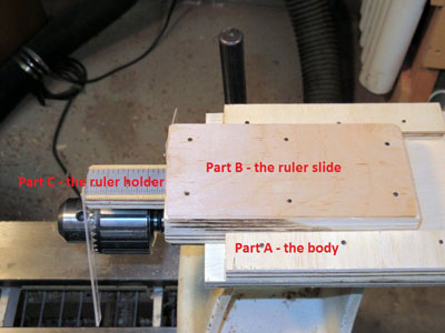
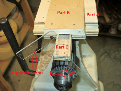
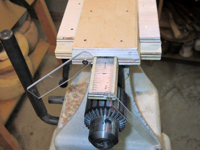
So…I decided to make a drill depth gauge to attach to my tailstock (Figures 2 and 3). The requirements
are simple:
-
Easy to make
-
Cheap to make
-
Allow the starting point to be set on the gauge
-
Allow the ending point to be determined right on the gauge (without the need for a separate
measuring tape)
|
|
Figure 2 - Drill depth gauge on tailstock, top view
|
|
|
Figure 3 - Drill depth gauge on tailstock, front view
|
My drill depth gauge sits on top of the tailstock, attached with two
Rare-Earth Magnets. It adjusts three
ways:
-
The main body (part A) can be positioned forward or backward on the tailstock
-
The topmost platform (the ruler slide - part B) slides in and out of the main body
-
The lower, smaller platform (part C, the ruler holder) slides in and out of the ruler slide
To use it, I put it on top of the tailstock, where the magnets hold it in place. I generally align the rear
edge of the body with the rear of the tailstock, although that's not an absolute requirement. I then
move the ruler slide so that its front edge lines up with the front edge of the quill (which is never the
front of the tailstock body, because on my lathe, the Jacobs chuck doesn't go all the way in until the quill
is extended at least a half inch). I then extend the ruler holder to the desired depth. Last I move the
tailstock so that the tip of the drill bit touches the end of the work piece.
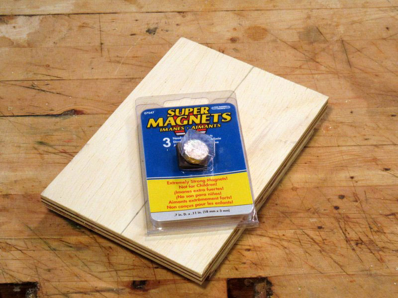
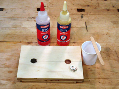
It's cheap – I used a piece of 1/2" plywood about 12 inches by 24 inches (and had a good bit left over), a
handful of small brads, some wood glue, two magnets, some epoxy glue, and some scrap plastic. It took
a couple of hours to build (well, after I made and rejected versions 1 and 2).
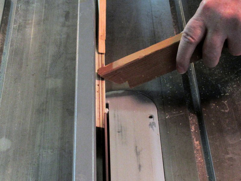
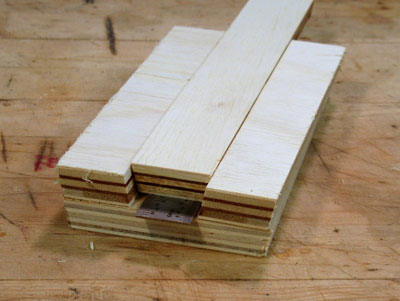
The Ruler Holder
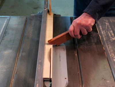
The ruler holder (part C) and the ruler slide (part B) both side between cleats that are beveled at 10
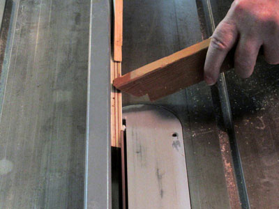
degrees on both edges. So I started by cutting one long 24 inch length of plywood, about 1-1/4 inch wide
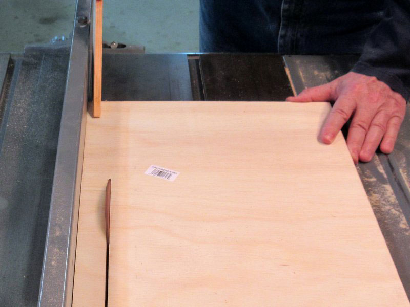
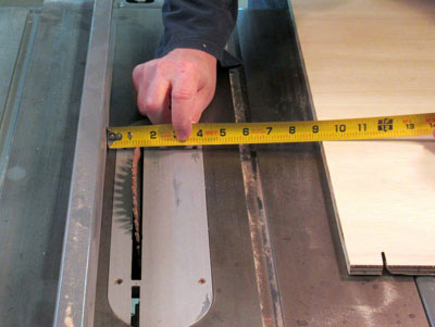
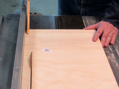
(at the widest surface), with the table saw blade set at 10 degrees (Figures 4 and 5).
|
|
Figure 4 - Set the widest point of the cut to 1-1/4 inches
|
|
|
Figure 5 - Cut a 24 inch length
|
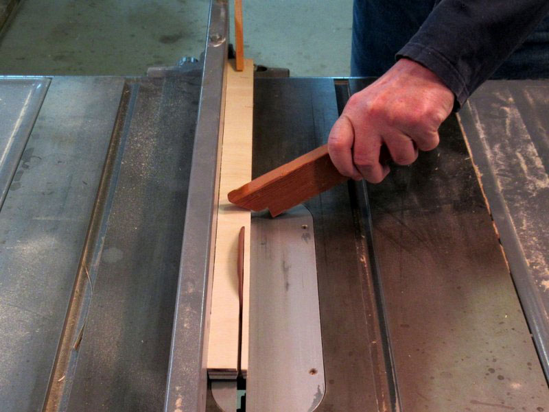
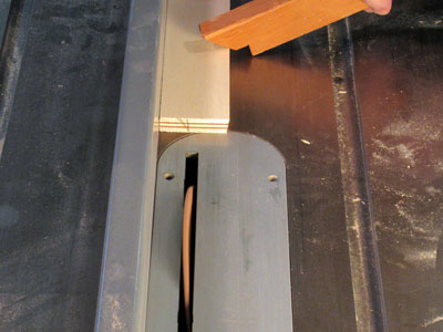
I repositioned the fence and cut the other side of the piece to a 10 degree bevel (Figure 6), to get bevels
on both sides of the cleats.
|
|
Figure 6 - Cut the other side of the cleats piece
to 10 degrees
|
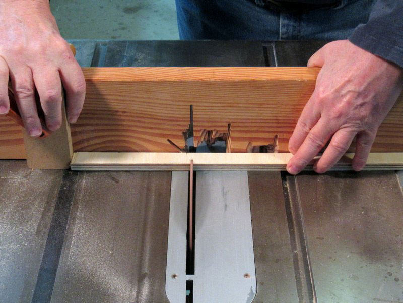
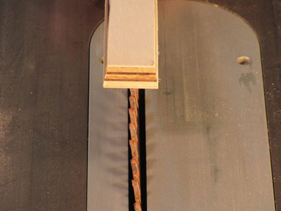
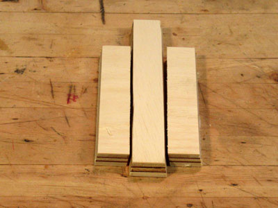
I swapped the fence for a miter gauge, and cut the 24 inch length into 4 cleats, each slightly less than 6
inches long (Figure 7).

|
|
Figure 7 - Cut the 24 inch length into 4 pieces
|
The ruler holder, the piece of wood that the ruler is glued onto, can be just about any length, but the
width must be at least as wide as the ruler. I used a ruler about 3/4 inch wide, and decided to make the
ruler holder around an inch wide at the top (the top is the narrowest part). The ruler holder is also
beveled at 10 degrees on both sides – it will slide between two of the cleats.
|
|
Figure 8 - The first cut on the ruler holder
|
|
|
Figure 9 - The double-beveled ruler holder
|
|
|
Figure 10 - The ruler holder positioned between
two beveled cleats
|
The ruler holder and its two cleats have to be fastened together somehow, and that somehow is a piece
that goes over the top of the slide and cleats. That piece is as long as the cleats, and as wide as the ruler
holder width plus the width of the two cleats (Figure 11). The addition of that piece turns the ruler
holder and cleats into the ruler slide.

|
|
Figure 11 - The ruler holder and cleats, upside down,
on top of the plate which holds them together
|
Just to make it look good, I cut the top piece with beveled sides also (Figure 12).

|
|
Figure 12 - The ruler holder in the ruler slide assembly
|
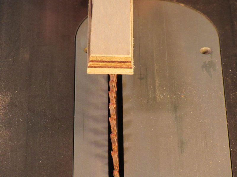
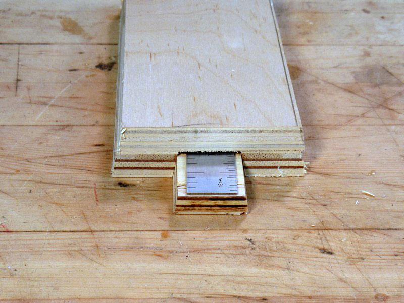
The ruler holder is the same thickness as the two cleats, which is not surprising, as they are all cut from
the same piece of plywood. However, the holder must have a ruler attached to its top (Figure 13), which
will cause the holder to be a bit taller than the cleats – this will interfere with smooth motion. So, I cut about 1/8 inch off the height of the slide. (Figure 14)
|
|
Figure 13 - The ruler sitting on the top of the ruler slide
(the slide assembly is upside down)
|
|
|
Figure 14 - Cutting the height of the slide
so the ruler will fit nicely
|
Now the ruler slide assembly is ready to be assembled (Figure 15).

|
|
Figure 15 - The ruler slide assembly, dry fit
|
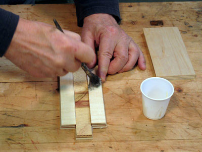
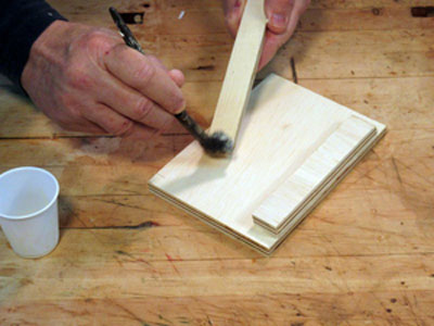
I assembled the ruler slide with yellow wood glue and brads to hold things in place while the glue dried
(Figures 16 and 17).
|
|
Figure 16 - Putting glue on the bottom of the cleats
|

|
|
Figure 17 - Short brads are used to hold the parts together
while the glue sets
|
The Ruler Slide
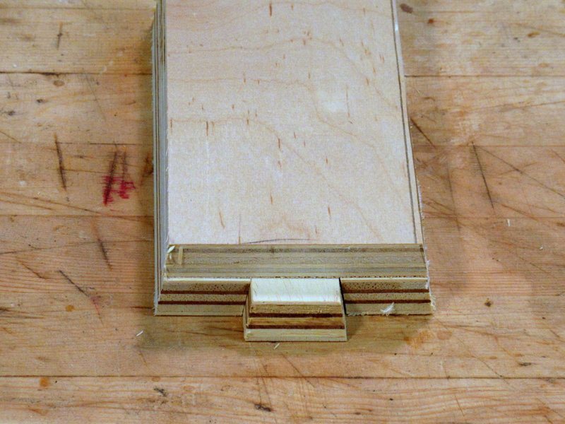
The ruler slide assembly has to slide on something, and that something is part A, the main body with
two beveled cleats. This is the bottom of the gauge. It doesn't slide itself, but it provides the sliding
surface for the ruler slide assembly.
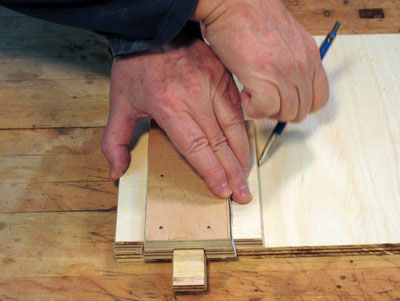
I held the glued-up ruler slide between two cleats on top of a piece of plywood and marked off the
width (Figure 18).
|
|
Figure 18 - Measuring the width of the platform
to hold the ruler slide
|
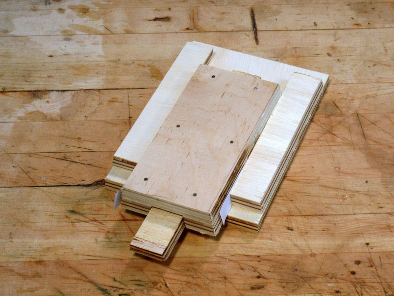
After cutting the body piece to width and length, I put the parts together with strips of paper between
the slides (for a slight spacing) to check the fit (Figure 19).

|
|
Figure 19 - The two platforms, ready to be glued together
|
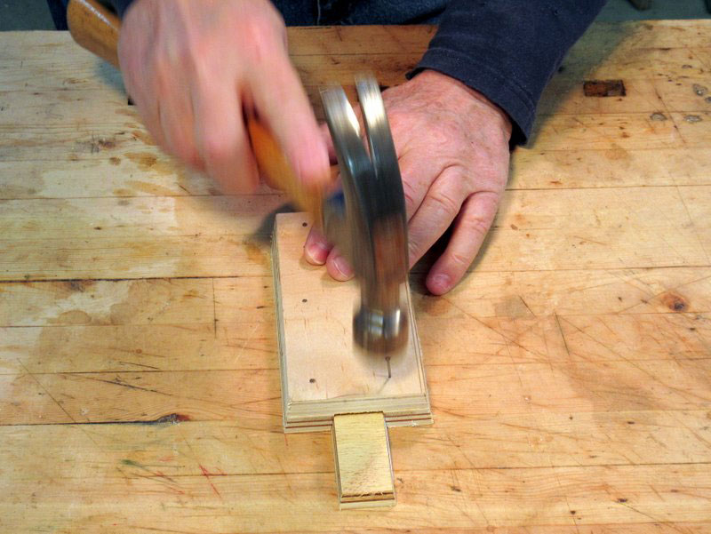
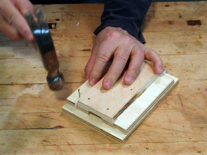
As I did with the ruler slide assembly, I put glue on the bottom of the cleats, and tacked them together
with small brads (Figures 20 and 21).
|
|
Figure 20 - Apply glue to the bottom of the cleats
|

|
|
Figure 21 - Attaching the cleats with brads
|
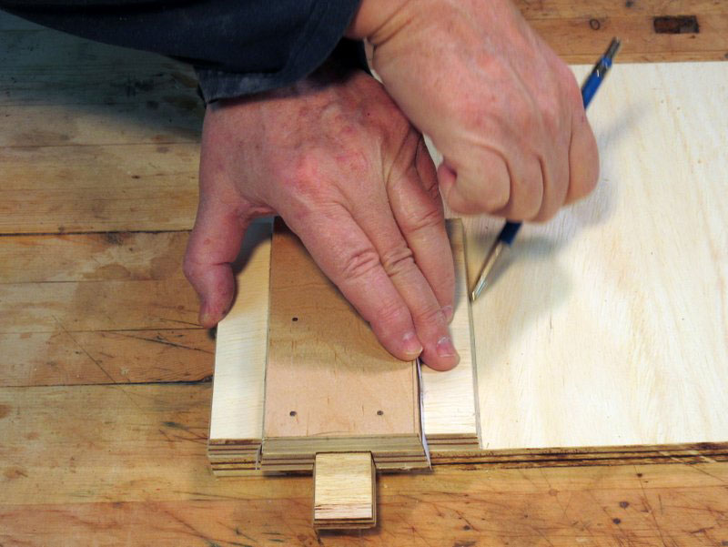
After the glue dried, I eased all of the corners and rechecked the fit. If it had been too loose, I would have
used a few strips of masking tape inside the cleats to tighten it up. If it had been too tight, I would have
used a block plane or the table saw to remove some wood from the side of the ruler slide. (Okay, I admit
it, it was a little too tight.)
The Magnets for Attaching to the Tailstock
Rare-earth magnets are very strong for their size, and I use them around the workshop to temporarily
hold chuck keys or other small metallic objects. For attaching the drill depth gauge to the lathe's
tailstock, I used two 3/4 inch diameter magnets – they are a bit less than 1/8 inch thick (Figure 22).

|
|
Figure 22 - Rare-earth magnets for attaching the
completed gauge to the tailstock of the lathe
|
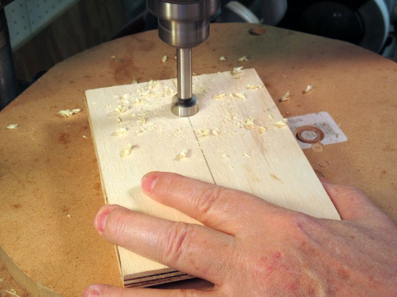
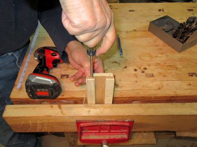
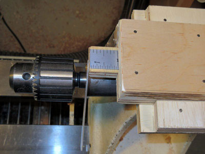
I recessed the magnets to their full depth in holes that I drilled in the bottom of the main slide (Figure
23). I put the holes about an inch from each end.

|
|
Figure 23 - Drilling a mounting hole for a magnet
|
I used epoxy glue to hold these magnets in place (Figure 24). Note the extra washer – a correction for an
over-exuberance of drilling!
|
|
Figure 24 - Gluing the magnets into
the bottom of the gauge
|
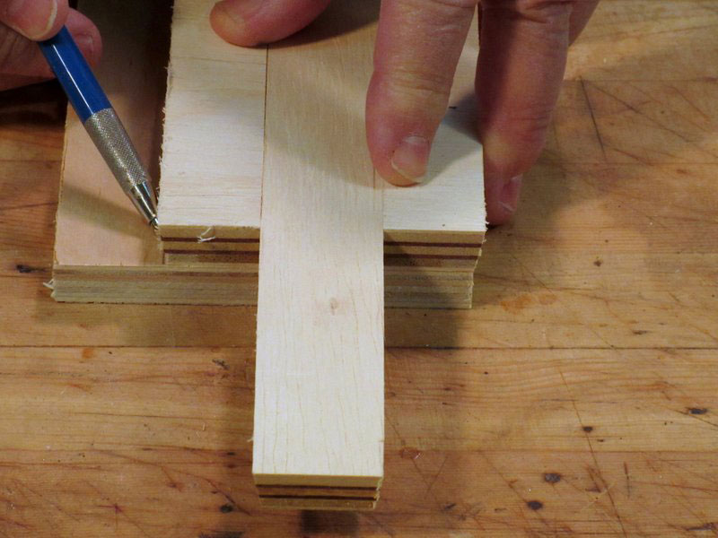
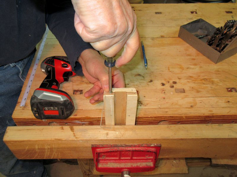
The Pointers
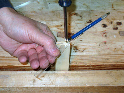
For ease of use, the ruler holder and the ruler slide each need a pointer that extends from the gauge
edge almost to the tailstock quill. I cut a couple of small lengths of plastic off some scraps I had laying
around the shop – about a sixteenth thick, and about a quarter to a half inch wide (Figure 25). It cut
pretty much like glass – score the cut line, then break it off.
|
|
Figure 25 - Cutting a piece of plastic to use as a pointer
on the end of the gauge
|
I decided to put the ruler slide pointer on the left side (if you're facing the tailstock). It extends down
and inward to the quill, and is held by a single screw so it can be rotated as needed (Figure 26).
|
|
Figure 26 - Attaching a pointer to the main slide
|
I fastened the pointer on the ruler holder to its right side with a single screw to allow movement (Figure
27).
|
|
Figure 27 - Attaching a pointer to the ruler slide
|
The Completed Drill Depth Gauge
Figure 28 shows the drill depth gauge mounted on the tailstock of my lathe.
|
|
Figure 28 - The pointers on the front edge
of the drill depth gauge
|
In use, I first set the main slide pointer (left side in Figure 28) to the head of the tailstock quill. It doesn't
matter how far the quill is extended, as long as the pointer will reach it (the main slide has a reach of 4
to 5 inches). I then slide the ruler out of its pocket to the desired reading on the ruler, and I adjust the
ruler pointer so that it clears the drill chuck, if necessary. Then the tailstock is moved up to the work
piece until the point of the drill touches the work. Then I just crank the tailstock hand wheel until the
tailstock quill reaches the ruler pointer (Figure 29).
|
|
Figure 29 - Drill until the front edge of the quill
reaches the ruler pointer
|
It's not microscopic accuracy, but it's good enough for me. If you build one, you will probably have to
modify the design to fit your tailstock, but the basic pieces should still work for you.
|
|
Figure 30 - The completed drill depth gauge
|
A nice enhancement would be a thumbscrew on the ruler slide and the ruler holder to lock each in
place. I haven't found that I need that, but it would be nice to have in case I'm drilling and there's a lot
of vibration.
If you have any questions you can email Rick at
carlrmorris@att.net