An Improved Knockout Bar for the Lathe
by Rick Morris
Duluth, GA
Note: Click on any picture to see a larger version.
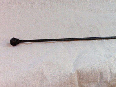
The knockout bar for a wood lathe is a pretty simple accessory – a long rod with a handle of some sort on one end.
|
|
Figure 1 - The knockout bar that came with my Jet 14-42
lathe 10 years ago
|
It's simple, it's effective, it's easy to use, and it's cheap to manufacture. So, really, could it be any better? (Hint: For the purposes of this article, the answer is yes.)
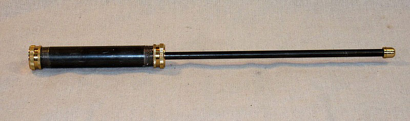
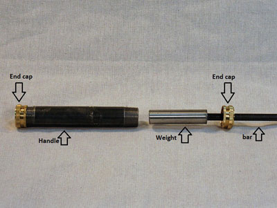
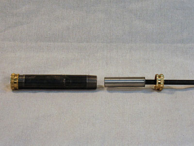
Below is my homemade knockout bar that incorporates a slide-hammer into the handle and a brass tip on the striking end. The slide-hammer handle adds weight to the knockout bar and the sliding action (back and forth on the left end of the bar) adds momentum to the strike to dislodge the drive center. The brass tip, softer than steel, ensures that the knockout bar will not flare or otherwise damage the end of the drive center when it is struck.

|
|
Figure 2 - My improved knockout bar
|
This knockout bar is easy to make and takes very little in the way of materials. It requires only a few metalworking operations – 2-3 cuts, two holes drilled, and (for me) about 10 trips to the hardware store for more bits and pieces to correct my mistakes.
Materials Needed
-
A 3/8" diameter rod, at least 24" long
-
A 3/4" diameter rod, at least 3" long
-
A 3/4" black pipe nipple, 6" long
-
Two garden hose brass caps (3/4")
-
A brass flare cap, 1/4"

|
|
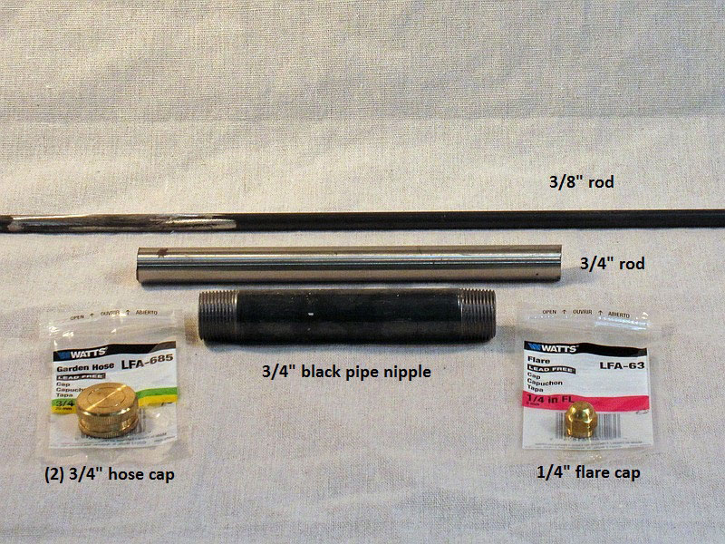
Figure 3 - Materials needed to make the knockout bar
|
The 3/8" rod is the bar part of the knockout bar. It fits the three lathes that I am familiar with – a Powermatic 3520b, a Jet 14-42, and a Rikon 12-24. Before buying this rod, check the size of the hole going through your headstock spindle to see if it's at least 3/8" in diameter.
The 3/4" black pipe nipple is the handle of the knockout bar. The short length of the 3/4" rod is the weight that is epoxied to the end of the bar that fits into the handle and slides back and forth. The two brass hose caps close the handle on each end, and the brass flare cap is the striking head of the bar.
Tools Needed
-
A hacksaw or angle grinder with a cutting blade
-
A drill press, or a Jacobs chuck and scroll chuck for your lathe
-
A centering drill bit (optional)
-
A 3/8" drill bit (metal-cutting twist drill)
-
Some epoxy
Making the Knockout Bar
There's not a whole lot of "making" to be done. Here is a brief summary of the steps:
-
Cut the 3/4" rod to 3" long
-
Drill a 3/8" hole in one end of the 3/4" rod
-
Drill a 3/8" hole in one brass hose cap
-
Glue the 3/8" rod into the hole in the 3/4" rod
-
Glue the brass hose cap without the hole onto the black pipe nipple
-
Put the holed brass hose cap onto the 3/8" rod
-
Slip the 3/4" rod (with the 3/8" rod attached) into the open end of the black pipe nipple
-
Glue the brass hose cap on the rod onto the end of the pipe
-
Cut the 3/8" rod to length for your lathe
-
Cut the brass 1/4" flare cap to a smaller diameter
-
Glue the flare cap onto the end of the 3/8" rod
Simple, right? Since a picture is worth a thousand words, I will go into detail on each step of the process.
|
|
Figure 4 - How the knockout bar is assembled
|
A heavy weight is attached to the bar and enclosed in the handle between a solid end cap (left) and an end cap with a hole (right), through which the bar moves.
The Sliding Weight
The 3/4" rod is just the right size to fit inside the 3/4" pipe nipple. The inside diameter of 3/4" black pipe, schedule 40 (plain non-galvanized pipe), is just a bit larger than 3/4". The short 3/4" rod will be the weight backing up the bar (the 3/8" rod). The pipe nipple is 6" long; the 3" long 3/4" rod will travel 3" back and forth inside the pipe.
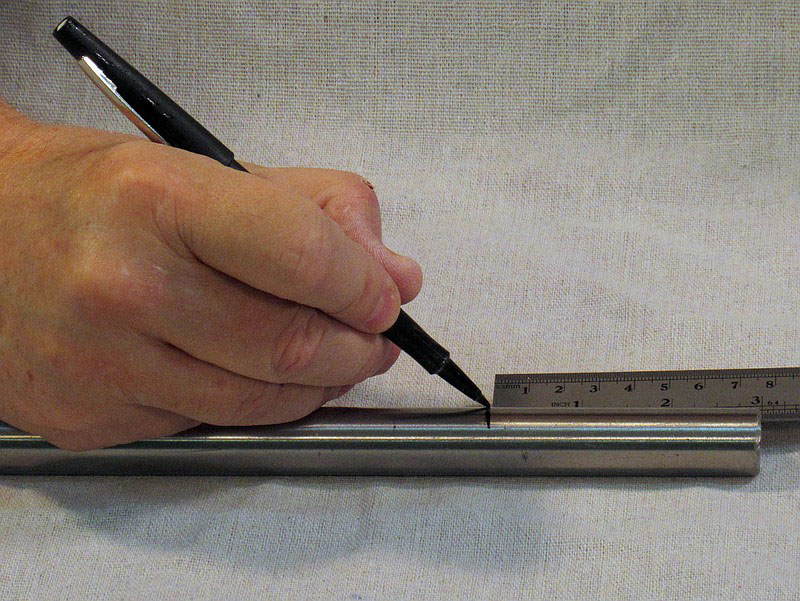
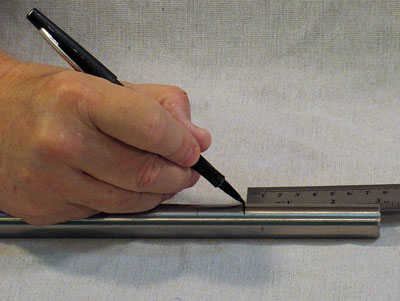
The first step is to cut the 3/4" rod to length – 3" long (Figure 5).
|
|
Figure 5 - Mark off 3" on the 3/4" rod
|
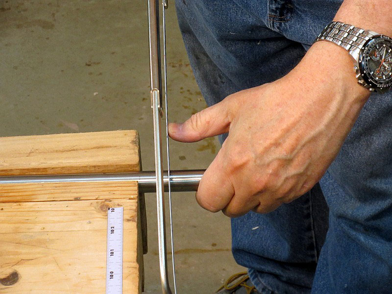
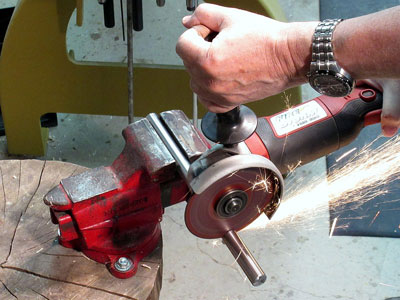
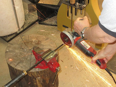
The cut can be made with a hacksaw (slow) or with an angle grinder with a metal-cutoff blade (fast), as shown in Figures 6 and 7.

|
|
Figure 6 - If you've got the patience, use a hacksaw
to cut the 3/4" rod...
|
|
|
Figure 7 - ...but if you don't have the patience, use an angle
grinder with a cutoff wheel
|
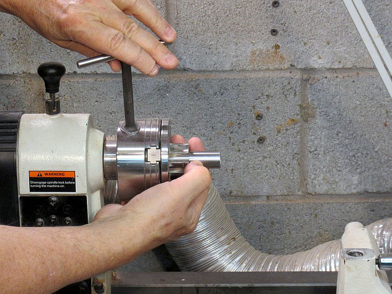
The weight must have a 3/8" hole bored into one end. Depth isn't particularly important; I drilled halfway in, to 1 1/2", to give a larger gluing surface. This hole can be drilled with a handheld power drill, a drill press, or a Jacobs chuck on a woodturning lathe. I used the Jacobs chuck because it's more fun.

|
|
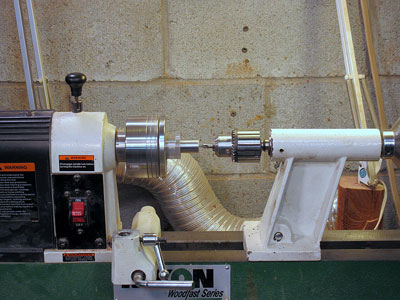
Figure 8 - Mount the weight into a scroll chuck on your
woodturning lathe
|
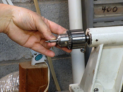
Start the hole with a centering bit, a small very rigid drill bit (Figure 9). If you don't have one, it isn't absolutely necessary – it's just nice to have, as the small hole will allow the larger bit to start cutting at dead center, rather than possibly wandering a little bit.
|
|
Figure 9 - A centering bit in the Jacobs chuck
|
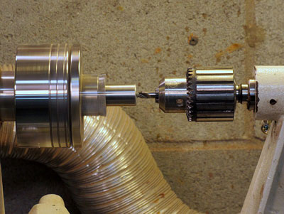
Bring the tailstock up to the end of the weight (Figure 10), switch on the lathe (use a low speed), and start drilling.
|
|
Figure 10 - Position the tailstock so that the tip of the
centering bit is right on the weight
|
The centering bit doesn't cut very deep. I drill until the chamfer at the right of the bit starts to cut (Figure 11). That slight chamfer makes it easier for the larger drill bit to get started.
|
|
Figure 11 - Slowly advance the tailstock quill until the
centering bit reaches its chamfer
|
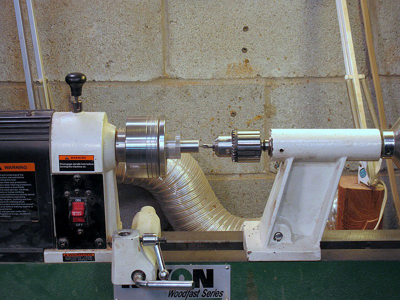
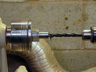
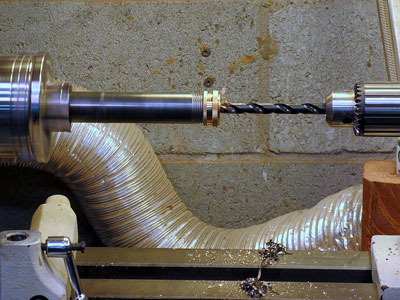
Pull the tailstock back and remove the centering bit. Mount a 3/8" twist drill in the Jacobs chuck. (Don't try to use a wood bit here – a brad-point bit, spade bit, or Forstner bit will not work well on metal.)
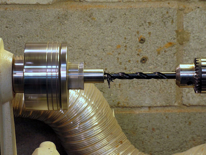
Once again, move the tailstock up, turn on the lathe, and start drilling the 3/8" hole (Figure 12). The depth isn't critical, but you do want a good gluing surface. I drilled halfway through, 1-1/2". This will take a little while – advance the tailstock quill slowly, and occasionally withdraw the drill bit and drip some oil on it to reduce heat buildup.
|
|
Figure 12 - Drill a 3/8" hole in the weight, 1-1/2" deep
|
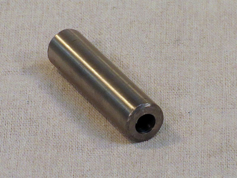
|
|
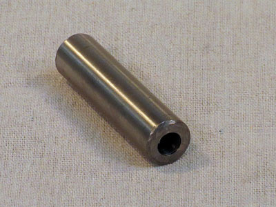
Figure 13 - The bar weight after drilling
|
While you've got the 3/8" bit on the lathe, drill the hole in one of the end caps (only one – the other one is left whole) (Figure 14). The end cap is a little too wide for the jaws on my chuck, so I screwed it onto the pipe and mounted the pipe in the chuck. This hole goes quickly – it's drilling into brass, and thin brass at that.
|
|
Figure 14 - Drill a hole in one of the end caps
|
Assembling the handle
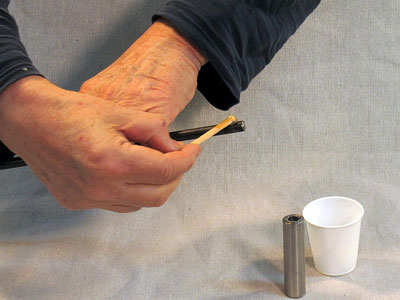
The handle can be put together now. Just in case, test fit the 3/8" rod into the hole in the weight, and make any adjustments that are necessary. Then put some epoxy on the end of the rod (Figure 15) and onto the inside of the hole, and glue the rod into the weight (Figure 16). It is (hopefully) a snug fit, so don't put on too much epoxy – it will just be squeezed out, or if it's a tight fit, it will prevent the rod from going all the way into the hole.
|
|
Figure 15 - Put some epoxy on the end of the bar…
|
|
|
Figure 16 - ...and glue it into the weight
|
Put that aside to let the glue cure.
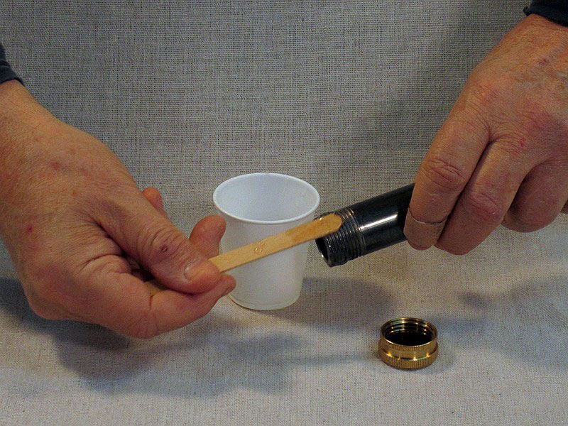
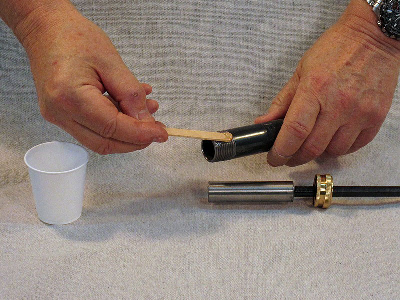
Still using the epoxy you just mixed up, spread some on the threads of one end of the pipe nipple and screw on the hose cap that doesn't have the hole in it (Figures 17 and 18).

|
|
Figure 17 - Put some epoxy on the end of the pipe...
|
|
|
Figure 18 -...and screw on the un-drilled hose cap
|
Give the weighted bar and the capped handle time for the epoxy to set.
…… tick tick tick ……. tick tick tick ……. tick tic-- oh, to heck with it, let's get started again…
|
|
Figure 19 -The handle parts are ready to be assembled
|
Slide the hose cap with the hole over the far end of the bar and move it down to the weight. Mix up some more epoxy and spread some on the remaining uncapped end of the handle (Figure 20). Slide the weight into the handle and then screw the hose cap onto the handle (Figure 21).

|
|
Figure 20 - Put epoxy on the uncapped end of the handle
|

|
|
Figure 21 - Screw the remaining hose cap onto the handle
|
Once again, give the knockout bar time for the glue to set.
Sizing the Bar
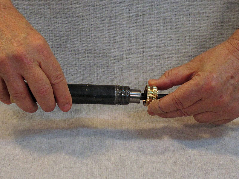
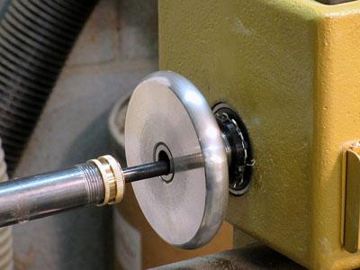
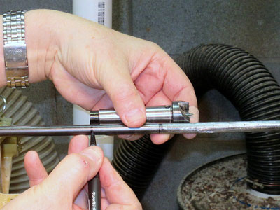
Now, you need to determine the final length of the bar. Position the handle to its rightmost limit on the bar, then put the bar into the hole of the headstock of your lathe. Move the knockout bar forward until there is about an inch between the rightmost end of the handle and the handle wheel (Figure 22).
|
|
Figure 22 - Position the knockout bar about an inch to the
left of the hand wheel
|
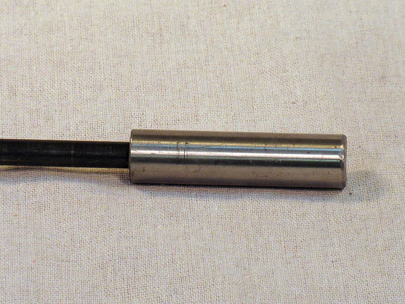
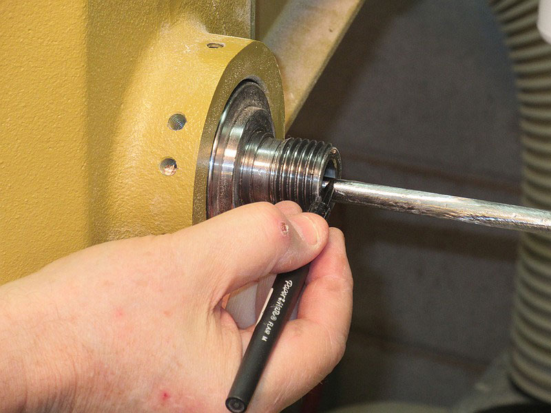
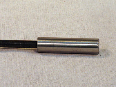
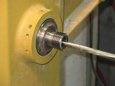
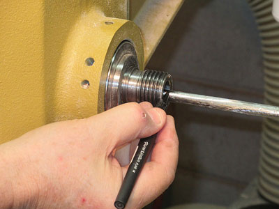
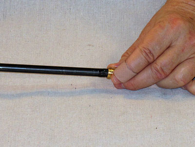
On the right side of the headstock, the knockout bar should be protruding at least a few inches beyond the end of the drive spindle (Figure 23). Use a felt-tip pen to mark the bar at the end of the spindle (Figure 24).
|
|
Figure 23 - The knockout bar protruding from the
headstock spindle
|
|
|
Figure 24 - Mark the bar
|
At this point, you have your best opportunity to screw things up (I speak from experience). You may shorten the bar beyond the mark you just made. The mark you have is actually several inches longer than the "perfect" length – because, once the drive center is in the spindle, the point the knockout bar hits it will be 2-3" leftward – the length of the drive center (Figure 25). So, if you haven't made any other positioning slip-ups, you can cut the bar 2-3" to the left of the first mark.
|
|
Figure 25 - Shorten the cutting length by the length of the
drive center
|
However, a couple of things can go wrong, so be very careful about reducing the length. First, if you have the handle slid to the left instead of to the right, your measurements are off by 3". Second, the drive center doesn't go all the way into the spindle – most likely, a half inch or so sticks out of the spindle when it is fully seated. So don't subtract the full length of the drive center. Third, the length of drive centers is not a universal constant – I checked three, with a variation of up to 1/2".
My recommendation is to cut to the length first marked (the front of the spindle). After cutting (Figure 26), put a drive center in the headstock spindle and gently slide the knockout bar until it touches the drive center. Observe how much of the bar is sticking out of the left end of the headstock, and shorten as desired.
|
|
Figure 26 - Cut the knockout bar to final length
|
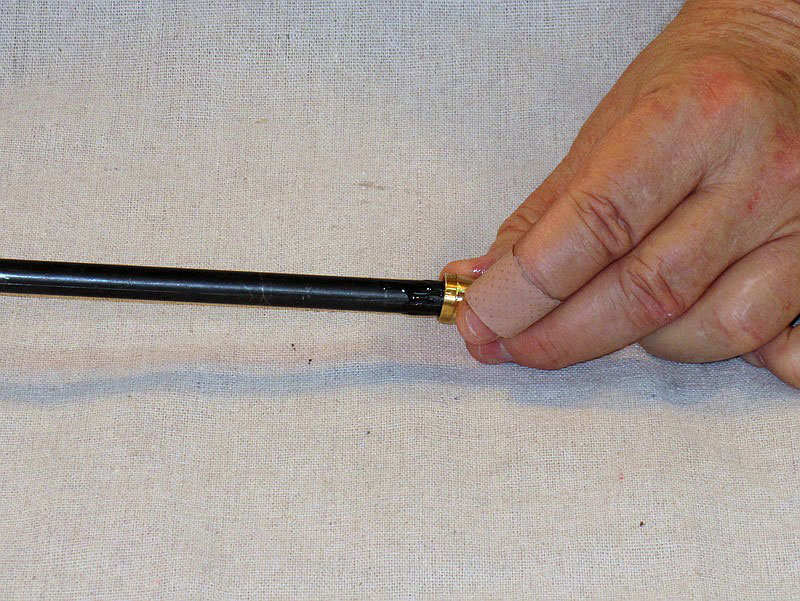
The final step (or two) is to attach the brass cap to the striking end of the bar. The 1/4" flare cap (in spite of the name, the opening in the cap is just over 3/8") will fit over the end of the bar. However, it may not go through the headstock spindle; on two of the three lathes I have used, the cap would fit after removing the nut flats. Slip the flare cap in the hand wheel hole to see if it will fit.
As I said earlier, I needed to make adjustments. With the nut flats on the cap, it would not go into the headstock spindle; with the nut flats removed, it would.
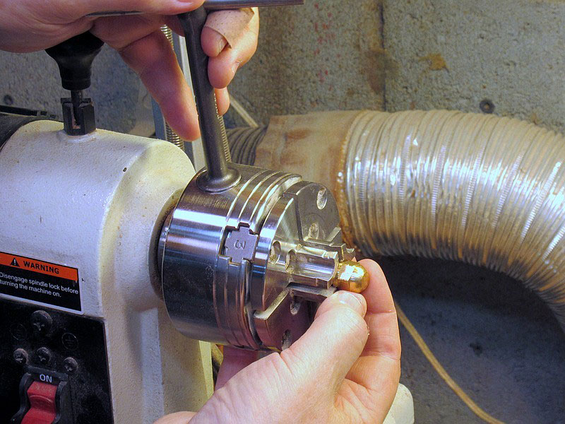
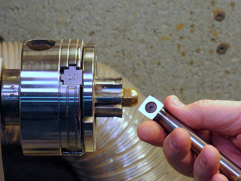
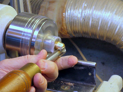
To remove those flats, some quality time with a metal file will do the trick, but that's no fun at all. I clamped the nut into my small-jaw scroll chuck (Figure 27), and used a homemade carbide-tipped turning tool (Figure 28) to turn off the flats. The cap is brass, and cuts fairly easily with a carbide-tipped tool (Figure 29), and even with a regular turning tool.

|
|
Figure 27 - Hold the flare cap in the scroll chuck
with small jaws
|

|
|
Figure 28 - Use a carbide-tipped tool to cut
|
|
|
Figure 29 - Cut the diameter of the cap down to what fits
in the headstock spindle hole
|
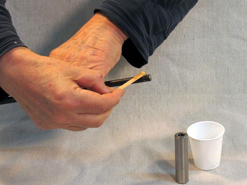
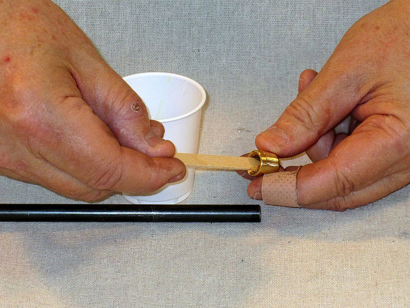
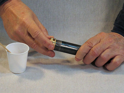
All that remains is to mix up some more epoxy, apply it to the flare cap (Figure 30), and glue the cap onto the end of the knockout bar (Figure 31). As with the gluing of the weight to the bar, don't put too much glue on – but in this case, the cap is a looser fit, and you want enough glue to fill the gap (some should ooze out when you push the cap on).

|
|
Figure 30 - Put some epoxy in the flare cap...
|
|
|
Figure 31 - ...and put the cap on
|
Conclusion
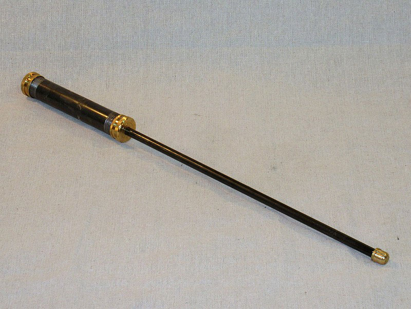
This slide-hammer knockout bar is ready to do some knocking-out (well, after the final glue up sets). Test it in the obvious way – your lathe, with a drive center.
Even when made out of such common materials, the brass knockout bar looks pretty good with the brass accents on either end of the black handle.

|
|
Figure 32 - The finished slide-hammer knockout bar
|
There are a few opportunities for more "customization":
-
You could wrap bicycle handlebar tape around the handle, for a cushioned grip.
-
You could use 1" pipe and a 1" diameter weight rod for a larger and heavier knockout bar.
-
You could use an angle grinder with an abrasive flap disc to make the bar and/or the handle shiny and silvery.
If you have any questions you can email Rick at
carlrmorris@att.net