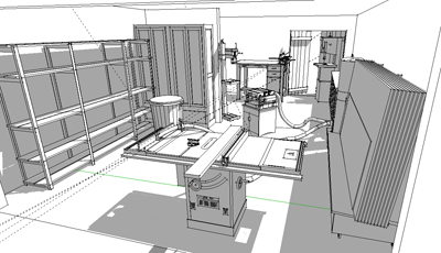
When I first started working with SketchUp, I wanted to create an inventory of shop tools with which
I (and anyone else) could create the ideal work space. Then by drawing the shop and downloading the tools
from the 3D warehouse, you can work on customizing the layout until you find the perfect solution for your
space and work flow. In this article we will go through the process of building your shop
environment, downloading the tools & accessories you will need, and then organizing them to maximize the
efficiency of your work flow.
Building your Shop
Start by opening a new SketchUp document. You will need the interior dimensions of your space including
any doors and windows that you want to represent in your model.
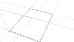
When I am laying out a space, I like to start by using the construction guides to lay out the
positions of the interior walls. With the guides set up, use the pencil tool to draw the interior
walls. Don't worry about the doors or windows at this point. The bottom edges of your walls should form a surface that
will be the floor of your shop.
To give the walls the proper thickness, use the offset tool. Hovering over the floor near one of
the walls, you will notice a red dot on the line that represents the interior wall surface. This dot
indicates the line your offset tool will be working on. You can pre-select lines in your model to
use the offset tool on. This tool seems to work best using the click and drag method. By this, I
mean it works best to click and hold the mouse button, drag the cursor to establish the exterior
surface of the wall, then release the button to complete the operation. As with most tools, you can
enter a value to determine the amount of offset.
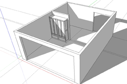
Next, use the push/pull tool to raise the walls to
the proper height, again typing in a value for an exact height. For the doors and windows, use the
rectangle tool to draw the openings on the surface of the walls. Then push/pull the face through the
wall to reveal the opening. You should make the shop a group now. By doing this, you can draw
tools, racks or benches into the space while keeping this new geometry separate from that of the shop.
Groups and Components
Understanding groups and components is critical to efficient modeling in SketchUp. Both are sets
of geometry that you've designated so that they can be selected, moved, rotated and copied together easily.
To make a group or component, you
select the geometry you want, right click, then choose "make group" or "make component" from the
drop down menu. You will notice a bounding box around the grouped geometry. With the move tool
enabled, you will notice grips that appear as you hover over the sides of the bounding box. These
grips allow you to rotate the group around an axis perpendicular to that face. To edit a group or
component, you can choose "edit group" or "edit component" from the drop down menu or simply double
click on the group to open it for editing.
There are a couple main differences between groups and components that should be noted. First,
each instance of a group is independent from other groups, while components are more like "clones"
of one another. When you edit a component, all the instances of that component will change
accordingly. Also when you create a component, it will show up in the "in model" category in your
components window. You can also create component libraries of parts, like cabinet hardware that you
use frequently. There is also a difference worth noting between their relative file sizes. As large models can get
difficult to work with, keeping the file size as small as possible is ideal. To illustrate what I am
saying, we can look at a dining room chair. Eight instances of that chair as "groups" would equate to
8x the file size of one chair, whereas eight instances of that chair as a component would be
substantially less. There is a lot more that could be said on this subject, but for now let's keep
these differences in mind.
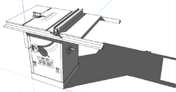
3D Warehouse
The 3D warehouse is a database of thousands of user-created models that you can search using
keywords for specific models or collections of models. There are collections of woodworking tools,
shop accessories and just about anything else you need to create your shop. As I mentioned at the
beginning of the article, I have uploaded quite a few tools and accessories for the shop, as well as
furniture models. Just type "sean headrick" into the search window and select the "search for
models" option. I try to make a practice of uploading any models that I think others might find
useful.
You can access the 3D warehouse by choosing
FILE> 3D warehouse> get model
from the toolbar at the
top of your modeling window. A separate window will open allowing you to search the warehouse for a
specific model or just browse. Once you have selected a model, you will have the option to download
directly into your model or into a new modeling window. One important note about components you
download from the warehouse is that they are made into a component when they are uploaded. For
instance, if someone were to load several components into the 3D warehouse, you will notice they
would be grouped into a single component when you download them. You can explode into the original
components by selecting the downloaded model, and choosing "Explode" from the right-click drop down
menu.
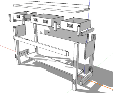
Setting Up Shop
Now that you have built your work space and gone on a virtual shopping spree in the 3D warehouse,
here are a few things that you want to keep in mind when setting up your shop. When moving tools
around in your shop, you will find that the "move" tool can sometimes seem erratic or hard to
control, especially if you are not familiar with it. I have a way of moving things around in my model that I
use almost all of the time. First, select the item you want to move. Now, use the "move" tool on a
line in your model that is parallel to the direction you want to move the item you selected. You
will notice the item you selected moves in relation to the direction and distance of the "move"
tool. If you want to line up to another point in your model, hold the shift key while moving along
either the red or green axis. This will confine the movement to that direction. You can then move
your cursor to line up with a point in your model. This technique works well in the blue (vertical)
axis, when placing things on the floor or on a shelf or table top.
Vacuum System Layout
Now that you have your shop all set up, the next step is to set up a dust collection system. There
are a couple of approaches you could take here. I have supplied a model in the 3D warehouse which you
can link to from
here
. As I mentioned earlier, you will want to "explode" the model once when you
download it. In this model, you will find that all the fittings are built in the same way. The
gates, Y fittings, and reducers are components with two groups nested within. One group is the
fitting itself. The second group is the beginning of the hose. This technique may seem a bit
complicated at first, but here is a brief description if you want to give it a try.
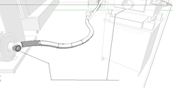
Start by double clicking the Y-fitting on the dust collector. Next double click on the ring inside
the fitting. This is the profile you will use along with the follow-me tool to create a hose. You
must be in edit mode of the hose profile when you create the route your hose will travel. You will
probably find it easiest to start by roughing out your path with straight lines using your "pencil"
tool.
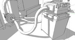
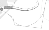
Then, go back and use the curve tool to create a "flowing" path for your hose to travel. Once
you have a path you are satisfied with, select the entire path, holding down the shift key to select
multiple sections. Then, with the follow-me tool, click on the profile of the hose to extrude it
along the path you selected. You can see the process here in these illustrations.
You can also build your vacuum system from the various hose sections that accompany the model.
With your "move" tool you can use the grips to rotate a selected hose section. Select a hose
section, and with the "move" tool hover over the faces of the bounding box around that component.
You will notice grips appear midway along the sides . Clicking on one of these grips will allow you
to rotate the component in that plane. When you begin to piece the hose sections together, you may
find it helpful to enable the "hidden geometry" in your model. This will give you some references
for lining up the sections.
I think you will find that doing a project like this will naturally promote an understanding of
how these tools work. So, have a good time building your shop, and don't forget to upload any tools
or shop machinery that you build. I can assure you there is someone out there looking for it.
Next month
we will look at some techniques and methods of work for creating a furniture model that can be
virtually disassembled to show every detail of joinery and construction.
Sean Headrick, a former Atlantan once seen frequently at Highland Woodworking, now lives
in San Jose, California where he does woodworking and design.
His website is
www.headrickdesigngroup.com
.
Sean was
interviewed by Wood News
in 2007.