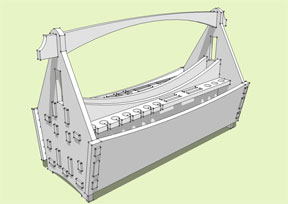
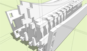
 This month I want to show you some of the techniques I used to build this toolbox in SketchUp. Once
you have created your design, I will show you the basic process I use to translate the information
in a SketchUp model into vector values that are used to produce the model on a CNC machine.
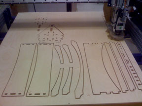
Where I live there is a woodworking store that makes available an entire shop for use by the
public. In addition to a complete line of woodworking tools and machinery, they also have a ShopBot
CNC router. Even if you do not have access to this type of facility, you may be able to find
businesses locally that offer CNC services to woodworkers and cabinetmakers.
This month I want to show you some of the techniques I used to build this toolbox in SketchUp. Once
you have created your design, I will show you the basic process I use to translate the information
in a SketchUp model into vector values that are used to produce the model on a CNC machine.
Where I live there is a woodworking store that makes available an entire shop for use by the
public. In addition to a complete line of woodworking tools and machinery, they also have a ShopBot
CNC router. Even if you do not have access to this type of facility, you may be able to find
businesses locally that offer CNC services to woodworkers and cabinetmakers.
Since the design is going to be cut from sheet goods, all of the thicknesses will need to remain
consistent. Mine is made from 1/2" plywood. It is strong enough to carry the weight, yet light
enough to easily carry around.
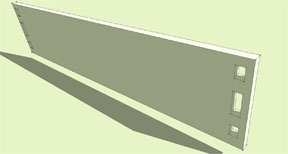
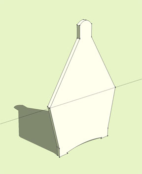 I started with the ends of the toolbox first. Create a rectangle 1/2" x 10" or so. This relates
to the thickness of the sides and the width. Use the push/pull tool to raise the rectangle up to
about 16". Using your
and your
pencil (or line) tool
, draw the profile you want
on the blank for your end piece. Then with the
Push/Pull tool
, remove the waste areas to reveal the
final shape. If you aren't satisfied with the shape, you can undo the last few steps and adjust the
shape to suit you. Once you have one end piece you will want to
make it a component
. Select the
entire part by triple clicking on it. Right click the selected geometry and choose "Make component"
from the drop down menu. Typically when I make a component I use the default name (component #1,
component #2, etc.) You can name the component (end, side, handle) before pressing "create" to
complete the operation. There are several other settings and controls in the component dialog box,
but they don't really apply to our project, so I will leave them until later to discuss.
I started with the ends of the toolbox first. Create a rectangle 1/2" x 10" or so. This relates
to the thickness of the sides and the width. Use the push/pull tool to raise the rectangle up to
about 16". Using your
and your
pencil (or line) tool
, draw the profile you want
on the blank for your end piece. Then with the
Push/Pull tool
, remove the waste areas to reveal the
final shape. If you aren't satisfied with the shape, you can undo the last few steps and adjust the
shape to suit you. Once you have one end piece you will want to
make it a component
. Select the
entire part by triple clicking on it. Right click the selected geometry and choose "Make component"
from the drop down menu. Typically when I make a component I use the default name (component #1,
component #2, etc.) You can name the component (end, side, handle) before pressing "create" to
complete the operation. There are several other settings and controls in the component dialog box,
but they don't really apply to our project, so I will leave them until later to discuss.
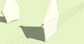
To make the other end of the toolbox, select the
move tool
. You will see by pressing the ctrl key
you are able to toggle the copy function on and off (indicated by a "+" symbol). Select the "end"
component and move a copy 20 to 30". I made mine 24".
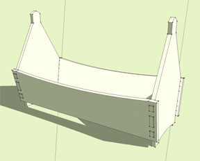
 As you can see from the finished model, the parts are all joined using mortise and tenon joinery.
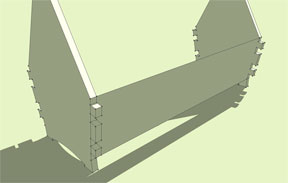
The next step is to add tenons to your end pieces that will join the sides of your box. Double click
one of the ends to enter the edit mode for that component. You can also right click and choose "edit
component" from the drop down menu. Create construction guides that will determine the top and
bottom of each tenon. Using the line tool, draw the location of each tenon and push/pull them out
about 5/8". This will allow the tenon to extend beyond the mortise by 1/8".
As you can see from the finished model, the parts are all joined using mortise and tenon joinery.
The next step is to add tenons to your end pieces that will join the sides of your box. Double click
one of the ends to enter the edit mode for that component. You can also right click and choose "edit
component" from the drop down menu. Create construction guides that will determine the top and
bottom of each tenon. Using the line tool, draw the location of each tenon and push/pull them out
about 5/8". This will allow the tenon to extend beyond the mortise by 1/8".
I think this toolbox would have good proportions making it 20 to 30" long, but you should decide
what looks best to you and suits your needs. Unfortunately you cannot simply scale the finished
model to get the proportions you like because scaling in either direction will cause some parts to
become thicker than the other parts, and your finished model will not fit together correctly.
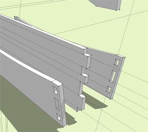
 For the sides of the box you will want to use the line tool to draw a rectangle from one end piece
to the other. I do not use the rectangle tool here because the bottom portion of my box where the
sides are connected are angled in a few degrees. The rectangle tool requires a zero-degree surface to
draw the geometry on. Use the push/pull tool to give the side a thickness of 1/2". You can see the
side will need to be extended 3/8" to 1/2" past the ends so you have material to cut the mortises
through.
For the sides of the box you will want to use the line tool to draw a rectangle from one end piece
to the other. I do not use the rectangle tool here because the bottom portion of my box where the
sides are connected are angled in a few degrees. The rectangle tool requires a zero-degree surface to
draw the geometry on. Use the push/pull tool to give the side a thickness of 1/2". You can see the
side will need to be extended 3/8" to 1/2" past the ends so you have material to cut the mortises
through.
The following steps are an efficient way to create a through mortise and tenon joint. Select the
face through which the tenons pass. Right click and choose
Intersect>Intersect with model
from the
drop
down menu. You will see that edges were created where the tenons pass through the sides. Now select
both end components, right click, and choose
Hide
from the drop down menu. Now you can simply
push/pull the mortises through to the other side. To unhide the ends choose
Edit>Unhide>All
from
the toolbar at the top of your modeling window.
To make the other side of the toolbox, first make the one you just completed a component by
triple clicking the side to select the whole piece, right click, and choose
make component
. Move a
copy to the other side of the box.
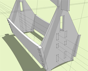
With the copy selected, choose the
scale tool
. Scale the side to
a value of -1.00. This
will flip the side into the proper orientation. To move the side into the correct position, use the
move tool, grabbing the corner of one of the mortises and dragging it to the shoulder of the mating
tenon. SketchUp will snap to to these points when you get close. Assuming you made the tenons on
both sides symmetrical, everything should fit correctly.
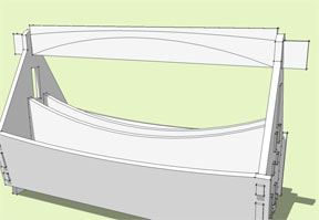
I also added a slight curve to the top edge of the side by double clicking to edit the "side"
component, using the curve tool to draw a slight curve along the top edge, then push/pull the waste
portion away. Having made the side a component, you will see this change occur to both sides.
 The process for making the bottom and the inside dividers is the same.
1. First create construction guides. This will help you keep everything symmetrical as you build. It
also helps you to visualize where different parts of your toolbox will be.
2. With construction guides in place, draw the profile in place and push/pull to create the part.
3. Select and hide the ends. Lay out the location of the tenons on both ends of your part, and
push/pull to create the tenons.
4. Unhide the "end" components and double click to edit.
5. Select only the outside face and "intersect with model". Selecting the entire part will cause new
lines to be created that will interfere when you try to push/pull the mortise through.
6. Hide the newly created part and double click to edit the end component. Push/pull the mortises
through.
 7. Unhide your new part, and make it a component. Copy and scale if necessary.
Most of the parts you will make for this project follow this procedure. In fact using this general
concept, I think you could make just about anything.
Follow these steps to make the tool holders using your own tools to determine the configuration.
I made the handle a little differently. I made the mortise first, then created a blank to draw
the handle on. However I believe the steps outlined above will work in almost every instance.
Prepare your model for export
 Now your toolbox should all be separate "groups" or "components" that you can arrange onto a flat
surface. Use construction guides to lay out the perimeters of your workspace. The machine I work on
can handle sheet goods up to 50" x 60". Find out the specifications of the machine that will produce
your project.
Now your toolbox should all be separate "groups" or "components" that you can arrange onto a flat
surface. Use construction guides to lay out the perimeters of your workspace. The machine I work on
can handle sheet goods up to 50" x 60". Find out the specifications of the machine that will produce
your project.
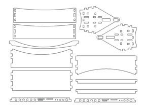
Using the "move" and "rotate" tools, lay all of the parts of your toolbox onto a single flat
surface, staying inside your workspace. I must admit that I am not very adept at this part of the
process, though whether you are renting time on one of these machines or having someone else
produce it for you, you will most likely be able to find someone to help you with the technical
parts of this step.
Many of you may be thinking that you cannot export your model unless you shell out for the pro
version of SketchUp. Good News. The newest version, SU 7.1, was just released allowing free version
users to export to Collada (*.dae) file format. While this doesn't quite compare to the multitude of
export options available in the pro version, the guys and gals at SketchUp seem to think this is the
most compatible format for 3D applications. You will need to go to the SketchUp website to download
the latest version.
Once you have arranged all the parts, choose the top view and turn off the perspective view.
These final two steps may be superfluous, but they can't hurt. Choose
File>Export>3D Model
. I
typically save to a flash drive, so pick the removable memory device from the "Save in" drop down
menu in the export dialog box. The file type should default to Collada. Name the file and press
"export." You can now take this vector information to the cut path generating software to make your
model.
I know there is a lot of information contained in this article. I have uploaded
a copy of this
model
to the 3D warehouse which you may find helpful to use as an aid when building your own model. I
would also suggest clicking the video links that describe the tools used in this project.
A couple final points I want to mention. As many of you are probably aware, you cannot cut a
mortise with square corners with the end mill used in this machine. As a last step before assembly,
you need to round over all the parts with a 1/8" radius bit (provided the cutter was a 1/4"
end mill). Also before you export, make sure the material you are using is the same thickness
dictated in your model. I use 1/2" Baltic birch which seems to work quite well with my material
thickness set at 1/2". If you need to you can adjust the thickness using the "tape measure" tool.
With this tool, measure the thickness of any one of the parts. The measurements box should read
1/2". Type in the thickness of the material you are using and press enter. A dialog box will appear
asking if you would like to resize the entire model. By clicking resize, the material thickness will
be adjusted along with all the related mortises.
I hope this article is helpful, and gets you thinking about all the neat projects you could design
using this concept. Please feel free to contact me via
e-mail
with comments or questions, as well as
suggestions for future articles. I would really like to see what some of you come up with.
Sean Headrick, a former Atlantan once seen frequently at Highland Woodworking, now lives
in San Jose, California where he does woodworking and design.
His website is
www.headrickdesigngroup.com
.
Sean was
interviewed by Wood News
in 2007.