 Last month we started the process of designing a kitchen renovation using
SketchUp
. We started the
process by modeling the building environment, showing the placement of doors and windows,
then adding moldings and door and window casings. We also saw how to use product documentation
and images from the Internet to make models of appliances and fixtures not already available in the
3D warehouse.
Last month we started the process of designing a kitchen renovation using
SketchUp
. We started the
process by modeling the building environment, showing the placement of doors and windows,
then adding moldings and door and window casings. We also saw how to use product documentation
and images from the Internet to make models of appliances and fixtures not already available in the
3D warehouse.
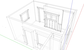
This month we will see how to make cabinets for the kitchen, create flat panel as well as glass
panel doors, then make drawers and add hardware to finish your kitchen design. The cabinets we are
modeling in this example communicate a good level of detail but are not meant to illustrate
construction details. Using the overall dimensions of each cabinet I normally create separate models
for more precise measurements and assembly
views. Once familiar with the techniques described here, you should have no problem creating all
types of cabinet models.
Base Cabinets
 I tend to start with cabinets that have to be a predetermined width like sink bases or microwave
cabinets, then build the remaining units.
I tend to start with cabinets that have to be a predetermined width like sink bases or microwave
cabinets, then build the remaining units.
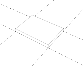
• Start by using
construction guides
to define the dimensions of your cabinet. A
standard base cabinet is 24" deep, so your base should be 21" deep to allow for a 3" toe kick.
• Use the
rectangle tool
to draw the base of your cabinet.
• Select the
push/pull tool
and raise the base 3".
 NOTE: To model accurately, you need to use the
measurements box
to enter values for the functions you
perform when modeling. If you do not see the measurements box at the bottom of your screen, you can
enable it by choosing
VIEW>TOOLBARS>MEASUREMENTS
from the toolbar at the top of your screen.
NOTE: To model accurately, you need to use the
measurements box
to enter values for the functions you
perform when modeling. If you do not see the measurements box at the bottom of your screen, you can
enable it by choosing
VIEW>TOOLBARS>MEASUREMENTS
from the toolbar at the top of your screen.
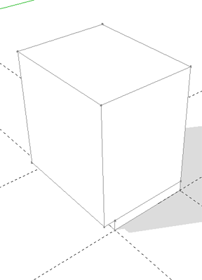
• With the push/pull tool still selected, press the control key. You can see this will
toggle on and off a "+" symbol next to your cursor. This allows you to create a new face. I think
this is especially useful for woodworkers as it helps to define where joints would occur. With the
"create new face" option on, pull the base up 31.5". This should bring the height of the base
cabinet up to 34.5" (36" standard counter height less 1.5" for the counter top)
• Push/pull the front of the cabinet forward 3".
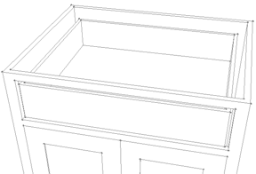
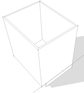 • With the
offset tool
, hover over the top of the cabinet. You will see the edges that
will be affected by the tool. Offset towards the inside of the cabinet 3/4". This defines the
sides, face frame, and back of the cabinet.
• With the
offset tool
, hover over the top of the cabinet. You will see the edges that
will be affected by the tool. Offset towards the inside of the cabinet 3/4". This defines the
sides, face frame, and back of the cabinet.
 • Push/pull the new face down 30.75" to leave a 3/4" bottom in your cabinet.
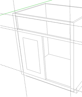
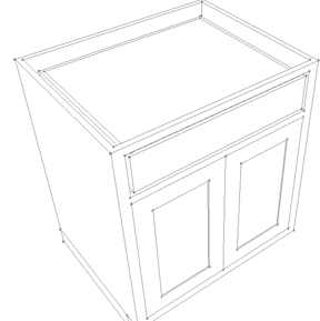
• Using construction guides, lay out the locations of the openings in the front of your
cabinet.
• Choose the rectangle tool. Using the construction lines you made, draw rectangles where
the drawer and door openings will be.
• Push/pull the faces through to create the openings.
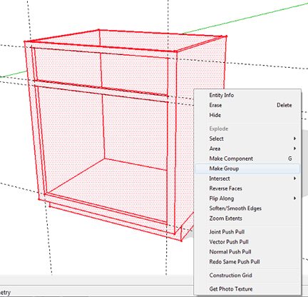
• You should now make the carcase a group by
triple clicking the object to select
all
the geometry, right click, and choose
Make Group
from the drop down menu.
Doors
 These steps will describe how to create flat inset panel and divided light glass doors. Once
familiar with the process you should be able to create many different door styles.
These steps will describe how to create flat inset panel and divided light glass doors. Once
familiar with the process you should be able to create many different door styles.
• Using the rectangle tool, draw your door starting from the upper left hand corner to
the center point along the bottom of the opening. (
SketchUp
will infer to center points
and end points as your cursor passes over them).
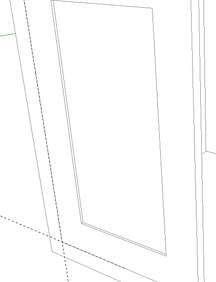 • Push/pull the face of the door in 3/4" for flush inset doors or out for overlay
doors.(For overlay doors you will also need to push/pull the edges to create the amount of overlay
for your specific application.)
• Push/pull the face of the door in 3/4" for flush inset doors or out for overlay
doors.(For overlay doors you will also need to push/pull the edges to create the amount of overlay
for your specific application.)
• For frame and panel doors, use the offset tool on the face of the door to determine the
width of your rails and stiles, then push/pull the face of the panel in 1/4" to 3/8".
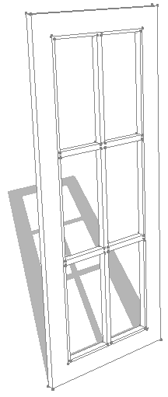
• For glass doors, begin the same way. Once you have offset the width of your rails and
stiles, right click on the line that is the inside edge of the stile of your door. Choose
Divide
from the drop down menu. This will create more or fewer divisions as you move up and down the line.
As I mentioned, center points are always recognized, so dividing the rail is not necessary unless
you plan on having more than two panes of glass from side to side.
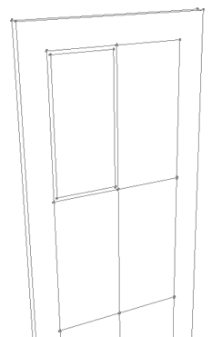 • With the line tool, draw lines dividing the space based on the divisions you set up in
the previous step. These will be the center lines of the glass mullions.
• With the line tool, draw lines dividing the space based on the divisions you set up in
the previous step. These will be the center lines of the glass mullions.
• Choose the offset tool. With your cursor in one of the panes, offset 3/16" to 1/4". Do
this in each one of the divisions until you have created offset rectangles in all of the
panes. (Double clicking with the offset tool creates the same offset as the last time the tool was
used).
• Erase the center lines you created in the previous step.
 • Push/pull the area where the glass will be located through creating the divided
lights, then push the mullions back about 1/4".
Make all the door geometry created thus far into a group
.
• Push/pull the area where the glass will be located through creating the divided
lights, then push the mullions back about 1/4".
Make all the door geometry created thus far into a group
.
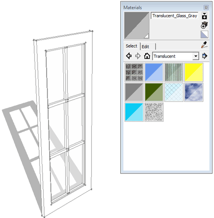
• To make the glass, draw a rectangle onto the back of the whole grille.
• Choose the
paint bucket/materials
tool. A dialog box will appear. Click to expand the
material drop down menu and choose
Translucent
from the material options. Select one of the
materials (I use the greenish type glass) and apply the material to the rectangle you made.
 • With the selection tool, while holding the shift key to select multiple items, pick the
"door" group and the glass. With your cursor over the selections, right click and choose
Make Component
from the drop down menu. This should be a component and not a group because you are going
to have multiple instances in your model.
• With the selection tool, while holding the shift key to select multiple items, pick the
"door" group and the glass. With your cursor over the selections, right click and choose
Make Component
from the drop down menu. This should be a component and not a group because you are going
to have multiple instances in your model.
• Select the new component and
Move a Copy
over to create a second door.
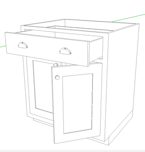
 Drawers
In this example we will model a flush inset drawer face. As before, once you understand the
concepts presented you should be able to create overlay drawer fronts using similar steps.
• Start by drawing a rectangle that matches the drawer opening.
• Using the offset tool create the drawer box by offsetting by 1/2". Depending on the
type of drawer hardware you use, you can adjust the clearance you need, but this should be accurate
enough for the purposes of this model.
• Select and delete the face around the drawer box.
• Push/pull the drawer box into the opening about 22".
• With the offset tool, double click the top of the drawer box repeating the last
measurement of 1/2" (a typical drawer material thickness).
 • Push/pull the new face created down approximately 1/2" shy of the total height of the
drawer box, leaving the drawer bottom.
• Push/pull the new face created down approximately 1/2" shy of the total height of the
drawer box, leaving the drawer bottom.
• Select the drawer and make it a group.
• For the drawer front, draw a rectangle matching the drawer opening as you did before.
• Push/pull the rectangle forword 3/4" to make the drawer front.
• Select the drawer front and the drawer box and make them a group or component.
• Select the drawer group/component. Using the move tool, click once on the corner of
the drawer front and click a second time on the corresponding corner of the drawer opening to place
it in the correct position.
To finish up your model, go to the
3D warehouse
to find the perfect knobs and drawer pulls . I
like these
bin pulls
for most of my drawers. I hope you find these techniques useful, whatever your
project. If you have any questions or article requests, please don't hesitate to
send me an email
.
Sean Headrick, a former Atlantan once seen frequently at Highland Woodworking, now lives
in San Jose, California where he does woodworking and design.
His website is
www.headrickdesigngroup.com
.
Sean was
interviewed by Wood News
in 2007.