In last month's article we constructed the #622 Stickley trestle table. In this article we will
use that model to see how tools such as "scenes" and "layers" can help make the information in your
model readily available when it is time to start building. You can download the model
here
.
LAYERS
Layers allow you to organize groups of geometry, or "furniture parts" for our purposes, into
separate categories that can be made visible or not in order to make assemblies or hidden details
more clear. It can also be used in conjunction with scenes to display specific views along with
relevant information and measurements.
Begin by opening your furniture model. It does not matter what model you use as long as each of
the parts are a separate group or component. Choose
Window>Layers
from the menu bar. This opens a
dialog box for managing the layers in your model. You can add or delete layers, toggle the
visibility of a layer, and select the active layer you want to work on.
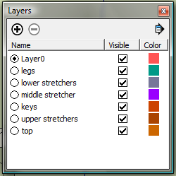
For this model we we will create a separate layer for each part or group of parts (e.g. table top,
legs, etc.) At the top of the layers dialog box, click the "+" symbol. You will see a new layer has
been added with a default label "layer 2". Name this layer "legs" and press enter. Create a separate
layer for each of the parts of your model. You may also want to make a separate layer for general
measurements or notes.
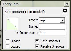
Next select
Windows>Entity Info
. This dialog box contains information regarding the specific
geometry, groups, or components currently selected. You can use the layers drop-down menu inside the
Entity info box to move the selected geometry to a different layer. With your select tool, select
all four legs, pressing the ctrl key to select multiple entities. Now select "legs" from the layers
drop-down menu. This moves the selected groups or components to this layer. Continue until all the
parts are in the appropriate layer. Try deselecting the visibility check box next to the legs. You
can now see the mortises in the upper stretchers as well as the tenons on the lower stretchers.
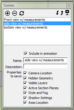
SCENES
As the name suggests, scenes allow you to save a particular view or camera position as well
as
shadow settings
, section cuts, and visible layers. SketchUp then will create smooth transitions
from scene to scene. There is also an option in your print dialog box that allows you to print the
scenes you have saved in your model. To open the scenes dialog box, select
Windows>Scenes
from your
toolbar. We will start by creating scenes of the standard views along with relevant measurements.
Choose
Camera>Standard Views>Front
from the toolbar. Also select the parallel projection view from
the
Camera
menu. This option will give you an elevation view of the front of your model. With the
"dimension" tool,
 add some general measurements to your model. Add another layer and call it "front
view measurements." Using the same technique as before, select the dimensions and move them to the
new layer you created. Now click the "+" symbol in the upper right corner of the scenes dialog box.
You may encounter a "Warning-Scenes and Styles" dialog box. The safe choice most of the time will be
the "Save as a new style" choice. The default name given to the new scene is "Scene 1." You can
enter a new name such as "front view w/ measurements" and press enter. Now the scene tab at the top
of the modeling window will show the name you chose.You can also enter a description just under the
name that will appear as fly-over text when you hover over the scene tab. Naming the tabs and
providing descriptions can be very helpful to refer to when relating your ideas to clients.
add some general measurements to your model. Add another layer and call it "front
view measurements." Using the same technique as before, select the dimensions and move them to the
new layer you created. Now click the "+" symbol in the upper right corner of the scenes dialog box.
You may encounter a "Warning-Scenes and Styles" dialog box. The safe choice most of the time will be
the "Save as a new style" choice. The default name given to the new scene is "Scene 1." You can
enter a new name such as "front view w/ measurements" and press enter. Now the scene tab at the top
of the modeling window will show the name you chose.You can also enter a description just under the
name that will appear as fly-over text when you hover over the scene tab. Naming the tabs and
providing descriptions can be very helpful to refer to when relating your ideas to clients.
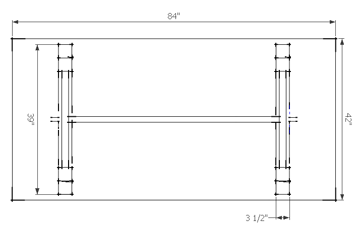
Go back to the standard views and select the left (or right) view. Add dimensions such as the length
of the table top and the distance between the legs. Add a new layer and name it "side view
measurements." With both of the dimensions selected, you will notice in the entity info box some
options for how the measurements are displayed. Try changing some of the settings to see how it
affects your dimensions. These changes can also be made by choosing
Windows>Model Info
, then selecting
the
Dimensions
tab. Before you add the scene you will want to make the "front view measurements"
layer not visible. To do this , uncheck the layer containing these measurements. You can now add the
scene and name it.
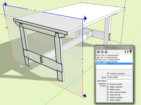
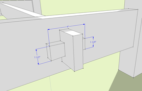
Scenes can also be quite helpful for showing details such as the key that locks the middle
stretcher in place. For views other than standard elevation and plan views, you will want to select
the
Perspective
view from the
Camera
menu. Orient your view so that the detail you wish to present
is framed in your modeling window. As before, create and name the new scene making sure only the
layers you want to be visible are checked. Fill out the name and description of the new scene and
press enter.
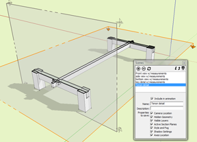
Another cool way of using scenes is to animate different section cuts of your model. While this may
not be the best example for this technique, I would be remiss if I left it out. Select the
 "section
cut" tool and hover over the different faces of your model. You will see that the section plane
orients to the face that you are hovering over. Click to place the section plane. You can then move
it to show a joinery detail or furniture component which might otherwise be hidden. Once you are
satisfied with the placement, add a scene. For a dramatic effect, add another section cut
perpendicular to the first. Add another scene and don't forget to name your scenes.
"section
cut" tool and hover over the different faces of your model. You will see that the section plane
orients to the face that you are hovering over. Click to place the section plane. You can then move
it to show a joinery detail or furniture component which might otherwise be hidden. Once you are
satisfied with the placement, add a scene. For a dramatic effect, add another section cut
perpendicular to the first. Add another scene and don't forget to name your scenes.
Now choose
View>Animation>Play
from your toolbar. SketchUp will animate all of your scenes into a
little movie. If you want to, you can toggle on/off the
 button that displays the section planes. This
does not affect the section cuts in your model. You can also adjust the amount of time it takes to
transition from scene to scene, as well as the scene delay (amount of time spent at each scene).
Dialing down the scene delay to zero creates more of a fly-through animation.
button that displays the section planes. This
does not affect the section cuts in your model. You can also adjust the amount of time it takes to
transition from scene to scene, as well as the scene delay (amount of time spent at each scene).
Dialing down the scene delay to zero creates more of a fly-through animation.
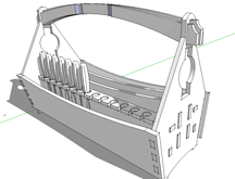
This should be enough to get you started making your SketchUp furniture models a bit more useful
for creating detailed shop documents as well as communicating your designs to others. Next month we
will see how to build a model of a toolbox similar to the one pictured that can be produced on a CNC
router.
Sean Headrick, a former Atlantan once seen frequently at Highland Woodworking, now lives
in San Jose, California where he does woodworking and design.
His website is
www.headrickdesigngroup.com
.
Sean was
interviewed by Wood News
in 2007.