3-D Furniture Design Using SketchUp
By Sean Headrick
San Jose, California
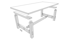
In this month's article I will walk you through the process of visually building a typical piece of furniture
that can be taken apart to provide any of the measurements or joinery details you will need when
working in the shop. We will be building a model of the #622 Stickley Trestle Table found in the
"Shop Drawings for Craftsman Furniture" by Robert Lang. Oftentimes throughout this article I will
make references to specific measurements in the model, however all the measurements are not in the
text. If you do not own a copy of the book you can
download the finished model here
to use as
reference. You should also note that some of the tools mentioned will be linked to a video that
explains the tool in greater detail. Unless you are already familiar with the tool, you will
probably find it helpful to watch them.
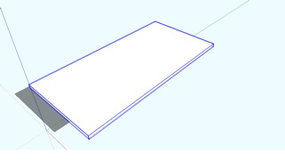
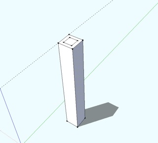
TABLE TOP
Start by using
construction lines
to lay out the perimeter of the table top. Looking at the plans I
can see the table top is 42" x 84" so I use the lines to lay out a rectangle that size. Then I will
use the rectangle tool to draw a rectangle the size of the table top. Using the
push/pull tool
raise
the table top to a thickness of 1.5". Now you should
select
the whole table top and
make it a
component
. By making the table parts into groups or components as you go, you are telling SketchUp
that these groups of geometry represent individual parts. The main difference between groups and
components is that all instances of a component will change to reflect changes made to a single
instance of that component in your model. With groups, changes made to one instance will not have
any effect on other instances of your model. Now select the table top component and
raise it 28.5"
.
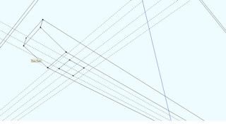
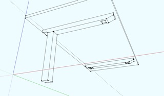
UPPER STRETCHERS
Create center line construction guides on the underside of the table top. I can see the upper
stretchers are 49.5" on center, 3.5" wide and 1.5" in from the edge of the table. Use construction
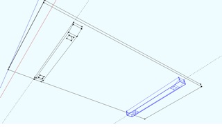
guides to lay out the position and size of a single upper stretcher. Draw a rectangle and use
push/pull to give it a thickness of 2.5". There is a bevel cut at either end of the stretcher with a
rise of 1.25" and a run of 3.25". Use guides (construction guides) to lay out these measurements on
the bottom and ends of the upper stretcher. Then use the "line" tool to draw the bevel on the side
of the stretcher. Push/pull the unwanted area through to the other face leaving it behind the bevel
cut. To complete the upper stretcher you need the mortises where the legs.
When I lay out
construction guides for a mortise and tenon joint in this sort of situation is to lay out the
position of the tenoned board on the mortised board with guides. Then, still with guides, lay out
the off set of the mortise and tenon. Draw a rectangle where the mortise will be located and
push/pull the mortise to a depth of 2 1/8". Once you have made both mortises, select all the
geometry and create component of stretcher. Now select the stretcher component and
move a copy 56.5"
.
Then with the copy selected click on the
scale tool
. While holding down the control key to scale
about the center of the component, scale the stretcher to a value of -1.00. This puts the stretchers
in the correct relationship to one another. Now when changes are made to the inside face of one
stretcher it will be reflected on the inside face of the other stretcher.
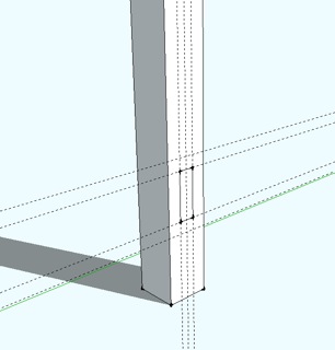
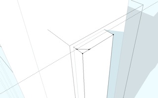
LEGS
In the last step of creating a mortise you laid out both the position of the mortise and the board
being joined there. You can use those layout lines to draw a 3.5" square for the leg. Next,
push/pull the leg to a length of 26.5". Triple-click the leg to select all the geometry associated
with it. Now, with all the geometry selected, right click and choose
Intersect>
intersect
with model
. Move your view to the top and select the table top and the stretcher where the leg is
located, right click, and choose
Hide
.
You will see that the location of the mortise was transposed
onto the leg to show where the tenon is located. Just push/pull the tenon a distance of 2" to
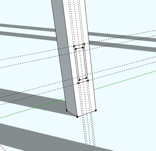
finish. Creating the mortise where the lower stretchers pass through the legs is the same process
as before. Lay out the position of the lower stretcher on leg using guides. Then lay out the off set
of the mortise and draw a rectangle to represent it. As this is a through tenon you will push/pull
the mortise through to the opposite face. Triple click the geometry of the leg to select ALL. Make a
component of the leg. When you do this, try clicking the drop down menu to "glue to" a horizontal
face. You will see that there is a shaded face that indicates that the component attaches to only
horizontal faces in your model. This is another difference between groups and components in that you
cannot give these attributes to a group.
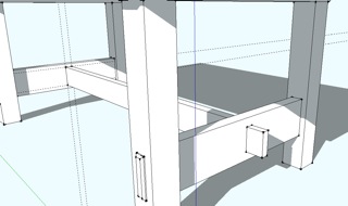
Now select the leg component and move a copy to the opposite end of the stretcher. Scale the copy
to a value of -1.00, for the same reason we did this with the upper stretcher. Now, select both legs
and move a copy to the other stretcher. Scale to -1.00.
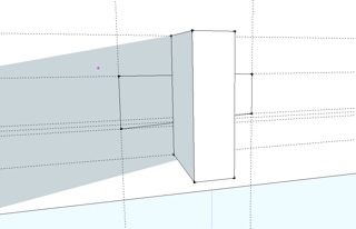
LOWER STRETCHERS
You should still have the construction guides from the mortise on the leg. Using the guides draw a
rectangle to represent the cross section of the lower stretcher. Push/pull to the opposite leg. This
tenon is a bit easier to do. Position your view to look into the mortise at the end of the
stretcher. Once there , draw a rectangle where your tenon would be located. Do this to both sides of
the stretcher. Use push/pull to extend the tenons flush with the leg, then 3/8" more.
To chamfer the end of the tenon you will want to zoom into get a close view of the end of the
tenon. Create a guide 1/4" in from the end of the tenon. Use your pencil tool to draw the profile
you will use with your "follow me" tool. Select the end face of the tenon then, with the "follow me"
tool click on the profile of the chamfer to have it follow the edges of the face you selected.
Layout and create the middle stretcher mortise the same as you have before. Once you have created
the mortise, select the entire lower stretcher by triple clicking it. Make into component. Move a
copy of the component to the other set of legs. Scale to a value of -1.00.
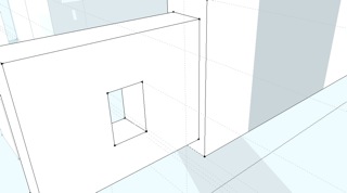
MIDDLE STRETCHER
Using the guides you created for the mortises in the lower stretcher draw a rectangle where the
middle stretcher is located. Use push/pull to extend the middle stretcher from one lower stretcher
to the other. Looking through the mortise in the lower stretcher at the end of the middle stretcher,
draw a rectangle where the tenon will be located. Push/pull the tenon flush with the outside face of
the lower stretcher, then 2-5/8" more. Do this to both ends of the middle stretcher. Triple click
the middle stretcher to select all of its geometry. Make component.
KEY
Use guides to lay out the shape of the wedge, or key, on the face of the lower stretcher. With the
line tool draw the shape of the wedge and push/pull to a thickness of 3/4". Triple click the wedge
to select all of its geometry and make component. Move a copy to the correct location at the other
end of the middle stretcher. With the wedges in place select both lower stretchers and "hide." Double
click the middle stretcher component to open it for editing. You should see that the rest of the
model is faded away except for the component being modified. Now triple click the middle stretcher
to select all of its geometry and right click, choosing
Intersect>intersect with model
. By hiding
both wedges you can see where the wedges pass through the tenon. Select and delete the faces where
the wedges pass through the tenon, then use the "pencil" tool to connect the corners on either side
of the tenon to make the inner faces of the wedge mortise.
Edit>Unhide>All
for your finished model.
I hope you found the information in this article helpful. You will find many more Stickley SketchUp
models from
Robert Lang's books on Craftsman style furniture
. Next month we will look at how to
view and display this model and see how to use layers and scenes to set up preset views with
measurements or notes. This is helpful in the shop but also when expressing ideas to your clients.
Sean Headrick, a former Atlantan once seen frequently at Highland Woodworking, now lives
in San Jose, California where he does woodworking and design.
His website is
www.headrickdesigngroup.com
.
Sean was
interviewed by Wood News
in 2007.
Return to
Wood News
front page