Don't tell me that I'm crazy; Don't tell me I'm nowhere
Take it from me…
It's hip to be square… It's hip to be square
--Huey Lewis & The News
Huey Lewis had it right. It is "hip to be square." It is also cool when wood is cut straight and smooth. A
shooting board and a good sharp plane assure you of always being hip… and square.
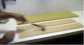
Figure 1. Shooting boards
are laughably simple affairs -
three boards, that's all!
Shooting boards are laughably simple affairs, but they are the go-to fixture for assuring square, smooth, very
"hip" cuts. The simplest consist of three boards. One large rectangular board, topped by one a little
narrower, with a third running perpendicular across the second to act as a fence. You have seen them, seen
them used, and maybe used one yourself. As long as the first board, upon which the plane slides, is coplanar
to the second, upon which the work piece rests, and the third board, upon which the work is aligned, is
perfectly perpendicular to the other two, a perfect ninety degree face can be cleanly and efficiently trimmed.
My trusty shooting board, perhaps the great- great- great-grandson of my first shooting board, was getting a
little "long in the tooth." Giving birth to a new one would typically involve about fifteen minutes of labor.
But, I decided to prolong the gestation period over a cup of coffee and think about whether the laughably
simple "classic" design could be improved.
After using the principles of 5S (you can read that article in our archives by clicking here) to streamline and organize my shop, I wondered why I still have 3 shooting boards? One each for 90-degree faces,
forty-fives, and for 45-degree tall miters (what some call a "donkey's ear" - no one seems to know why) might
be occupying more precious shop space than necessary. Perhaps a "universal" shooting board could be designed.
Lately I have been inclined to look favorably upon inclined shooting boards. Typically, with this design, the
plane rides along a flat register surface as with any conventional shooting board, but the work is held
against an angled work support with a perpendicular face/fence. Devotees theorize that by holding the work
piece on an inclined support, the plane slices through the wood at a slight angle (like skewing a plane across
a flat surface) and that more of the blade width is thus exposed to the work, thereby spreading the wear and
the dulling effects across more of its surface.
The theory about spreading out the wear seems a bit of a stretch. Plane blades are not overly delicate
instruments, and they stand up to a fair bit of use and abuse. The part about the plane entering the work
piece and slicing at an angle did appeal however, since I generally plane with the tool skewed. It just seems
to work better.
So instead of holding the work piece on an incline, what if the plane ran on an inclined runway? Perhaps the
plane could run downhill on the slice and up hill to draw the plane back for the next cut. Gravity could work
in my favor!
Because a right-handed person taught me to use his shooting board many years ago, I have always built them the
same way, even though I am left-handed. I wondered if it would be prudent to make an ambidextrous shooting
board. Using the plane on both sides of a shooting board really would even out the wear.
As a rule, my shooting boards reside on a shelf below my bench. This has proven workable, and definitely fits
the "5S" philosophy. However, there are currently about a dozen other important "close-at-hand" things under
my bench, and it is getting cozy down there. French cleat boards on three walls of my shop allow me to hang
anything with a matching 45-degree cleat, almost anywhere in the shop. I would like to be able to store my
new universal shooting board on the wall.
I would also like my new shooting board to be heavy and substantial. I would like it to be renewable, meaning
that I would like to be able to replace the high-wear parts, but not the whole shooting board. And, very
importantly, like every other shooting board I have ever built, it needs to be cheap. Preferably, made of
scrap.
With these criteria in mind, I was ready to build. What? "Yikes," you say! "He hasn't drawn a thing! He
hasn't even taken a measurement!" That is correct, and I apologize. There are no measured drawings for this
design. But, as stated before, shooting boards are simple affairs, and engineering and designing one would
seem at odds with the whole spirit of the affair.
A shooting board should be built quickly, easily, but most importantly, to fit your specific personal needs
and wants. Through the following photographs and description, you can follow my "seat-of-the-pants"
design/build process. You, however, should design and build your own shooting board. Make it fit your
workbench. Give it the features most important to you. Make it comfortable and make it yours. I just hope
my design will help inspire some great ideas. So, let's get going!
Rifling through the lumber rack yielded some very serviceable scraps of 3/4" MDF, 3/4" birch plywood, and various
other off-cut pieces. I also found a pretty badly cupped piece of 5/4 cherry culled from a recent project. A
couple of "shorts" of "big-box" 1" X 4" poplar were added to my rummage pile.
One large MDF piece looked perfect for the base, and it seemed to fit. It was long enough to overlap my bench
on both ends, and plenty wide. I checked it for square (which would not have really mattered) and found one
side slightly out. Truing it up on the table saw took only a minute.
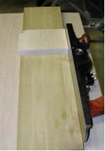
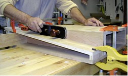
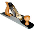
My jack plane is my preferred shooting plane (Low Angle Jack Plane, Item #434213), so I measured its height, top to bottom, and figured that when
laying on its side, in shooting position, it would need about 3 1/2" of runway width. More would be okay.
The best piece of scrap 3/4" birch plywood was long enough to form the top of the work support. I ripped a
section out 13" wide for the work support top and two runway strips 3 3/4" wide. From the scrap pile I ripped a
few more pieces of plywood to that same 3 3/4" width - they will be used later for the runway vertical supports.
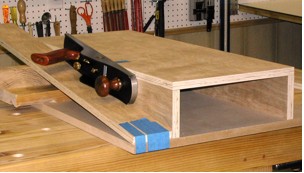
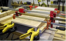
Figure 2. Tape, scraps, and clamps are all that are
needed to "mock up" the shooting board
and
start to get some measurements.
The next step was to figure out the correct height for the material support. Using some scraps, blue
masking tape, and a couple of clamps, it was easy to mock up the shooting board. Sliding the plane down the
improvised runway helped determine the right height.
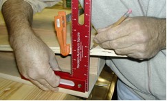
These are the important measurements: Where does the mouth of the plane intersect the cutting area throughout
the inclined slide path? Where does the blade first start making a cut, and at what point in its journey down
the runway does it no longer cut all the way through a 3/4" or 1" work piece? I marked those spots temporarily
with blue tape.
After a little "experimenting" it turned out that 4 7/8" was the correct work support height. Plywood pieces
were ripped to the correct width (4 7/8" - 3/4" = 4 1/8" in this example) to form the work support legs. As
with the runways, a few extra pieces of 3/4" ply were ripped to this same width and set aside. One of the
pieces was purposefully ripped with the face grain running across the short dimension.
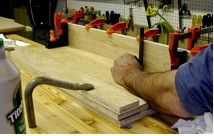
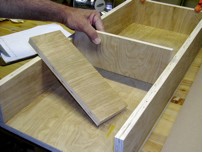
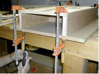
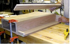
Figure 3. Work carefully when attaching the work
support legs, checking for square at multiple spots.
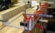
Figure 4. Double and triple check the work support
legs - the simply have to be square!
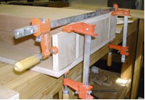
The first assembly step was to attach the legs to the work support. It is critical that the vertical legs
be perfectly square to the material support. If the "chute" faces are not perfectly 90-degrees to the work
support, the whole shooting board becomes worthless. Remember, it is "hip to be square."
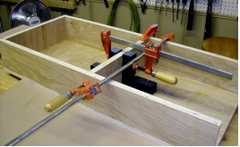
I used glue only. Although some fasteners were used later in the base assembly, even those were probably
overkill. Remember, the work support legs and the work support juncture must be at 90-degrees, so I braced,
clamped, triple-checked, and let the glue set for a good long while. I used the time to dress that cupped
piece of 5/4 cherry. After squaring the cherry completely, I re-sawed part of it to 5/16" thick and finish
planed the re-sawed faces, checking the square constantly.
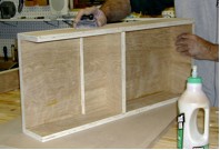
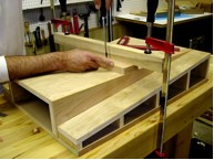
Figure 5. End support in place,
middle support being test fit.
After the glue had set on the work support legs I cut-to-fit one plywood end piece and two central support
pieces. The piece with the grain running across the short dimension became the end piece, just for looks. I
cut the pieces to fit, repeatedly removing a scintilla of material until the fit was perfect. If the pieces
were too long or too short, they could throw off that perfect 90-degree angle previously attained between the
work support and its legs. It was also time to make a decision as to which end of the work support would be
the front. The front, or "belly" side, of the shooting board got the end support. The other end of the
material support assembly stayed open.
Figure 6. Middle support is located just in front of the
line where work pieces will meet the fence face.
The middle support board was positioned directly under, and in front of, the blue tape mark made earlier…
the mark where the plane no longer cuts all the way through a work piece. In other words, I positioned the
middle support under and just in front of the eventual fence location. This will provide additional support
for the fence and prevent deflection of the work support. This middle support piece was glued into place, and
then the third piece was attached flat to the underside of the work support, on the far side of the fence
location.
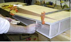
Figure 7. Center the work
support carefully on the base
and mark the location.
After the work support assembly was fully cured, I centered it on the base, perfectly square, and marked
the location by drawing a line down each side. Three-eighths inch in from these lines, 9/64" clearance holes
for #6 coarse thread drywall screws were drilled through the base, from the bottom, and the holes were
countersunk.
Figure 8. With a sanding block,
lightly sand away any glue residue
and make sure the sides are flat.
Before mounting the work support to the base, I sanded the sides lightly and then attached the slightly
oversize cherry "chutes" to the work support sides. These chutes form the surface along which the business
side of the plane will ride.
Figure 9. Even with "Extend" glue,
it is best to work quickly.
I like to use "Extend" glue and a "J" roller to apply a very consistent and even thickness of glue in this
application. The "J" roller is quicker than a brush. I glued both "chute" sides at once. No need here for
Herculean clamping power, just a lot of clamps, cauls, and even pressure. The chutes just need to be flat.
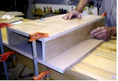
Figure 10. Clamps and cauls keep the
"chutes" flat during glue-up.
With the chute sides attached, it was then possible to get a very accurate measurement of the overall width
of the work surface. While the glue was setting, I started prepping more of the 5/4 cherry for fence
components. I made the fences a "hair" wider than the work surface. The first time the shooting board is
used, the plane will trim the fences to perfect width.
Figure 11. I like to glue and clamp
and then let the glue set for
fifteen minutes before
driving
the screws home. That way
there is less chance for
the work support to shift.
Attaching the completed work support to the base was next. With obsessive care to get it square, glue,
clamps, and then screws were added. I used #6 X 1 5/8" coarse thread drywall screws.
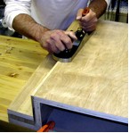
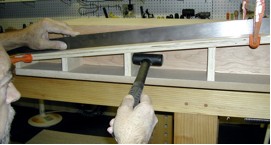
Figure 12. A couple of quick swipes with
the plane leveled the cherry sides
flush with the work support.
After the work support was affixed, I used my jack plane to trim the cherry chute sides flush so that the
surface of the material support was perfectly flat.
Figure 13. Time for one more mock up…
double check that the plane will make
a full cut at the fence face location.
With the work support attached to the base, it was time to mock up the runways again. I wanted to make
sure that the plane would cut fully through my thickest normal work piece (1 inch thick in my case) at the
fence location. When the runway was in the location I liked/needed, I measured the angle. In my case,
7-degrees (or 83-degree cuts) provided the necessary runway incline support.
Figure 14. Use a square to mark
the ends of the runways, set
the angle, and cut to length.
Figure 15. Cut the two end supports
for each runway and a few extra pieces
at the same angle to use as runway supports.
While still in mock-up, I marked the angles and ends of the runways, and cut them to length. Then I
clamped the runways into place again, measured, and cut the two end supports to length with one end of each at
the previously determined 7-degree angle. I used the extra pieces that were ripped earlier to match the runway
width. At this time I left the table saw blade set to 83-degrees and cut a few additional pieces for which
the overall length would be determined in a few minutes.
Figure 16. Check carefully here for
square, then glue the front and back
runway supports into place.
I glued the longer (front, belly-side) vertical runway support and the short (back, far-side) support into place, checking carefully for square.
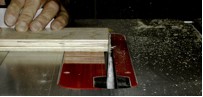
While the front and back runway supports were setting, I used an auxiliary fence on the table saw to cut a
1/8" X 1/8" kerf into the inside edge of each runway. These mini-rabbets provide egress for dust and small
shavings so that the plane always rides true and square to the fence.
Figure 17. Glue the ends only
of the runways into place.
After the front and rear runway supports were fully set, the runways were glued in place. It is very
important to note here that no glue was applied to the edges of the runways. Only the ends get glue at this
point.
Figure 18. Cut three supports from
the angled-end pieces cut earlier.
Place them into approximate position.
After the glue dried, I measured and cut three additional supports. Spaced roughly equidistant, mine were
1 5/8", 2 3/8" and 3 5/16" long. I cut two pairs of each length.
Figure 19. Adjust the runway until
it is absolutely flat and then
glue supports in place.
Using an absolutely certain straight edge, I checked for runway flatness. One runway was a little low in
the middle, so a quick tap of the interior supports with a light dead blow hammer nudged the runway into
perfect flatness. Similarly, if the runway had been high in the middle, clamps could have lightly pulled it
into place. This is why the edges of the runways were not previously glued to the sides of the material
support (the chutes).
Up to this point, I hadn't attached the French cleat or the bench hook, simply because I wanted to be able to
turn and position the shooting board on my workbench without hindrance during the construction phase. Both
pieces now got a liberal dose of glue and were attached with reinforcing screws.
Figure 20. Take all the time you
need with the fixed fence attachment.
Have a cup of
coffee.
Take a break.
But whatever you do, make sure
the fence is attached square.
The last critical step was to attach the fixed 90-degree fence. I paused for a minute to remember just how
hip it is to be square, and thought about how I would accomplish this critical step. No one would want to have
come this far in the design/build process and then ruin the whole shooting board by mounting the fence off by
a tenth of a degree.
I first drilled 9/64" clearance holes through the 90-degree fence using the drill press. Also, still using
the drill press, I milled countersinks. After clamping the fence into place, and quadruple checking the
square of the assembly, I used these clearance holes to drill pilot holes (3/32"), and drove home some long
screws. The screws had plenty to "grab" since the flat interior support piece on the underside of the work
support made it double thick in that area.
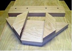
The next few photos show the construction and general shape of the miter and tall miter fences. The design
and size of these additional auxiliary fences will be somewhat determined by the size of your shooting board,
the available materials (scrap) you have on hand, and your creativity. Chances are, you will come up with
something better than mine. In fact, you will probably come up with all kinds of refinements as you design
and build your personal universal shooting board.
Figure 21. No, not a Klingon warship. From the off-cut scraps, two support wings were glued
to the 45-degree fence. These lay over the top of the fixed fence for stability and the open space in the
middle allows the fixture to be clamped to the fixed 90-degree fence.
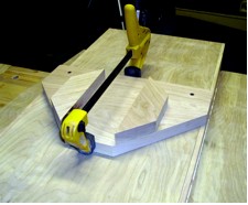
Figure 22. 45-degree fence clamped in place and ready to cut perfect miters on either side of the shooting board.
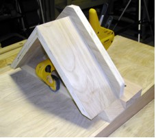
Figure 23. The tall miter fence, sometimes called a "donkey's ear" or "birdhouse" fixture is
also made entirely of scrap pieces. It too is clamped to the 90-degree fixed fence when in use and provides
ambidextrous access.
After a very light sanding and a coat of Watco Danish Oil, I added a couple of coats of paste wax to the
runways and chutes. Finally, I got to make my first test cut. "Sweet" does not even begin to describe it.
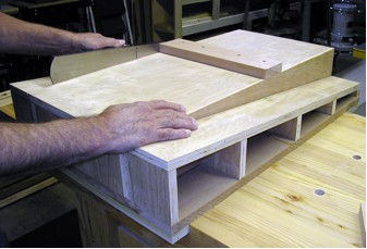
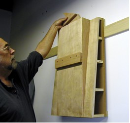
Figure 24/25. The finished shooting board. With inclined runways for the plane,
ambidextrous use, and multiple fences, this is a shooting board that will fulfill all my needs. Remember the
open end of the work support? When hanging on the wall, the open end provides convenient storage for the
auxiliary fences.
Are you ready to build your own custom, personalized shooting board? We would love to see photos of your creative design.
Please send to the e-mail address below. Just remember, "It’s Hip To Be Square!"
You can take a look at the Shooting Board I built in action in the video below:
Steven Johnson is recently retired from an almost 30-year career selling medical equipment and
supplies, and now enjoys improving his shop, his skills, and his designs on a full time basis
(although he says home improvement projects and furniture building have been hobbies for most of his
adult life).
Errors regarding pricing and specifications are subject to correction.
SOME SALE QUANTITIES MAY SELL OUT and become unavailable at the advertised price.