How I Built a Wood-bodied Smoothing Plane
by Lee Laird
Austin, Texas
Click on any picture to see a larger version.
 Contents
The Plane Iron
Choosing the Wood
Squaring the Blank
Marking up the Blank
Cutting the Blank
Determining the Bedding Angle
Cutting the Bedding Angle
Creating a Trough for the Screw
Glueing Up
Installing the Cross Rod
Making the Wedge
Cutting the Slot in the Sole
Adjusting the Blade and Using the Plane
Final Shaping of the Plane Body
Many woodworkers I’ve met have at least a couple of hand planes, and while most of them
seem to be iron-bodied planes, there are quite a few who also have some wood-bodied
planes. I equally fit into this scenario, and while my iron-bodied planes work
wonderfully, I also enjoy the feel and results of using wood-bodied planes. Before we move
forward, let's discuss the two main types of wooden planes, other than molding planes.
Originally, wood-bodied planes were made by taking a block of wood and
drilling/cutting/chiseling out the middle section where the iron/wedge would reside during
use. Since the block of wood was not cut open, ultimately limiting access, the level of
expertise and precision ran about 9 or 10 out of 10. A more recent iteration of the
wood-bodied plane was somewhat (if not completely) designed by James Krenov, where the
solid block of wood for the plane was cut into a few core pieces, both speeding up the
build process and allowing for the use of additional tools/techniques. In this article,
I'll focus solely on a style of plane that is a take on the Krenov designed planes. Two
significant differences are 1) my use of a metal cross-rod rather than a wooden one that
is trapped between the two sides, and 2) not using dowels to index the sides to the core
pieces. You can implement one or both of these design options during your build, if you
wish.
The Plane Iron
The first step in this build is to acquire the iron or iron/chip breaker combo you will
use, as this will provide certain key measurements in the process. You can use just about
any iron from a block plane or bench plane, if you would rather reuse something already in
your kit. I personally like the iron/chip breaker sets from Hock Tools, as they sharpen
easily, and take a wicked sharp edge. Additionally, they are 3/16" thick, which helps to
reduce (eliminate is more like it) chatter, which can be caused by micro vibrations of the
iron at the cutting edge. The Hock Tool sets are now offered in the original 3-1/2" length
as well as a longer 4-1/2" length. This extra long version can allow some additional
design choices, whether it is bedding angle or simply the shape of the body.
|
|
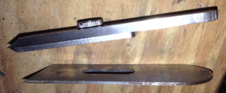
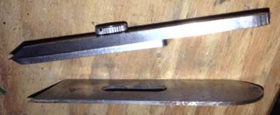
Figure 1 - Side view of Hock set above Stanley block plane iron.
|
I recently purchased two of the longer Hock Tools iron sets, created to use in a wooden
plane body built by the end-user. I decided to try both the 2" iron and a 1-3/4" iron, to
see how they behaved. In the following plane build, I am using the 2" iron, but I also
built a body for the second iron, and I'm finding that the overall size of the 1-3/4" iron
and it's body feel better in my hands. Before moving forward on any aspect of the wooden
body, make sure to sharpen/hone the iron up to 8000-grit, so the iron is exactly as it
will be in use and there are no surprises as you work through the build.
Choosing the Wood
Next up is to
find some hard wood that is suitable for the plane's body (kits are available for the
plane body, if you’d rather spend less time designing and just build). A few years ago I
found some Cherry that I had cut into rectangular blocks, from a half-log section. They
were around 3" square in thickness and 12"-14" long, which provided plenty of wood for the
smoothing style plane that I had envisioned. Another positive attribute was the fine grain
structure of this wood. While most hard woods are usable, it's not a bad idea to steer
away from some that have a more porous nature to their structure, as some oaks have.
Ultimately, it is up to the person making the plane. One nice thing about this type of
plane body is that you can always modify/adjust the body to your liking, and if it doesn't
work well, make another one.
Squaring the Blank
Before starting the layout, I squared up the Cherry blank using my jointer plane. If
you don't have a jointer plane or a powered jointer, you can flatten one side (which will
be used as the sole of your plane) using sandpaper on a known flat surface, like a piece
of float glass or the top of a table saw. Use a square to check if either connecting side
might just be square to the flat surface you created. If not, using the square with the
beam against the flat surface, mark each end of the blank. Draw a line down the length of
the blank, between the two points that intersect the side opposite of the flattened side
(shown in Figure 2 below as the dotted line running down the length). This will indicate
the amount of wood you need to remove in order to create the side square to the flat
side.
Repeat for the other side adjacent to the first flat side, so it is also square to the
original flat side.
|
|
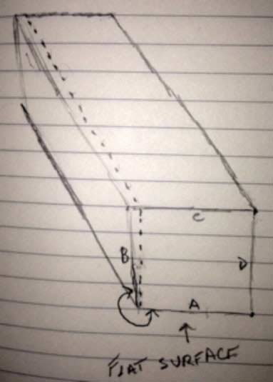
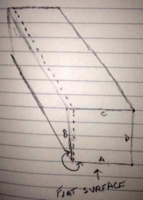
Figure 2 - Dotted line indicates square up end and down length. Original angle between A and B is larger than 90-degrees.
|
Marking up the Blank
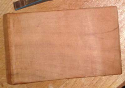
After the blank is square, draw a large triangle on the sole of the
plane, with the tip of the triangle pointing towards the toe of the plane. This will help
put the pieces back together, after cutting, in the same orientation as they were
originally. Hold the iron up to an end of the blank, with the iron centered, and mark
outside the iron by about 1/8” on each side. This extra space provides a little room to
adjust the iron laterally, while setting the plane for use. Set a marking gauge for the
distance between the edge of the blank and the marks made outside the iron. If cutting on
a bandsaw or a table saw, run the gauge down the top surface so you can easily line up the
cut. If cutting with a hand saw, run the lines down both of the long sides and along the
end grain.
|
|
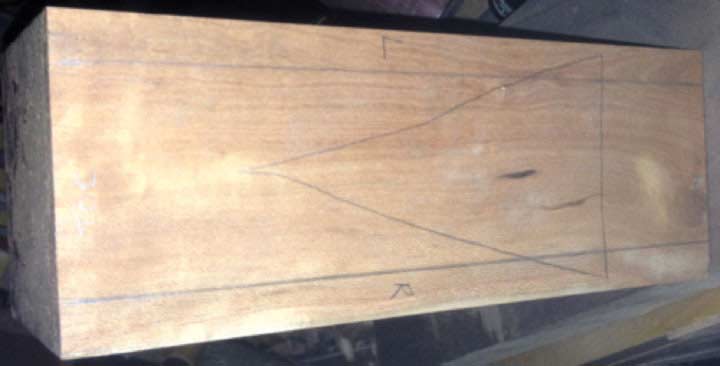
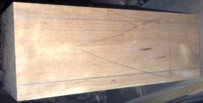
Figure 3 - Large triangle and side thickness marked.
|
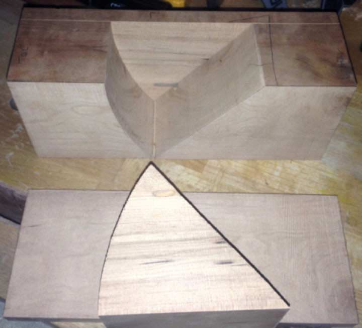
Cutting the Blank
Set up the bandsaw fence so the distance from the edge of the blank (touching the
fence) to a tooth on the blade that points away from the fence, almost touches the nearest
line on the blank. This will minimize the setup, as you can cut the first side and then
just rotate the blank so the opposite side is against the fence (keeping the same surface
down on the bandsaw table) and make the second cut. Always make sure to use push sticks,
especially when dealing with narrow off-cuts (like the sides for this plane). Safety must
be job number 1!
Before laying out the bedding angle and the front relief angle on the center section,
you'll need to determine if the inside surfaces of the three pieces need attention to glue
up solidly and gap free. If you have a carbide-tipped bandsaw blade, you may be golden
straight from the saw. If the surfaces do need attention, work carefully, trying to keep
your work as flat as possible. If sanding, use light pressure pushing the piece forward
with centralized hand pressure, and then lift and repeat. After the pieces mate well, set
aside the two sides and it's now time to mark the center section for cutting.
Determining the Bedding Angle
Most standard bench planes (smoothers, jacks, and jointers) have the iron bedded at
45-degrees. When making your first wooden plane, this is probably a good choice, unless
you already have a number of planes with this bedding angle or need a high-angled plane. I
actually made this plane with a bedding angle of about 50-degrees, which can help handle
some difficult grained woods. If you go with a 45-degree bedding angle, you can use a
combination square to mark the angle, as most have one side with a 45-degree angle. If you
want to go higher than 45-degrees, either you can use a sliding bevel gauge set with a
protractor, or you could mark out 45 degrees and shift it slightly to get into the 50 – 55
degree range. I wouldn't suggest going much higher than 55 degrees, even though there are
a few planes that are around 57-degrees, as the effort to push the plane through the cut
increases as the angle increases. When you decide the angle for bedding, line up the
bottom portion of the bedding angle so that it is closer to the toe of the plane, rather
than the heel. I have used the ratios of 1/3 or 2/5 the length from the toe, to find where
I'll mark for this angle. The other line you'll mark on the center section can be either a
straight line or a gently curved line. I prefer to use a curved line, as this gives a
little more room when reaching in to clear a shaving. The angle (this time sloping from
the sole upward towards the top) at the toe section is in the 70-degree range. If you want
a curve, just mark the upper and lower points on a 70-degree slope and then hand-draw a
gentle curve between them.
Cutting the Bedding Angle
To cut the bedding angle for the iron you can use the table saw
and miter gauge, a chop saw, or the bandsaw. The front section's cut is easiest at the
bandsaw, as it is not a critical cut and doesn't need to be absolutely flat for the iron.
I always expect to clean up the surfaces of both cuts. Check the bedding surface to make
certain there are no issues preventing solid contact with the back of the iron. To adjust
it, you can use a block plane set for a light cut, sand paper on a known flat surface, or
even a diamond flattening plate. I prefer to use the block plane and skewing it slightly
makes the work much easier. Just remember to focus on your technique so you don't impart
any unintended shaping to the surface. To smooth the front section’s surface, you can use
a hand scraper, a spindle sander, or even sandpaper over the mating surface of the
triangular leftover after the two cuts to the center section.
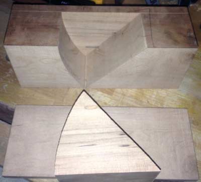
|
|
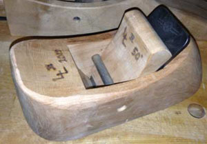
Figure 4 - All cuts made with side and center swung open.
|
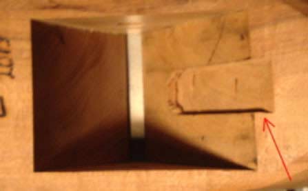
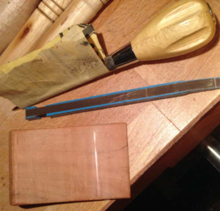
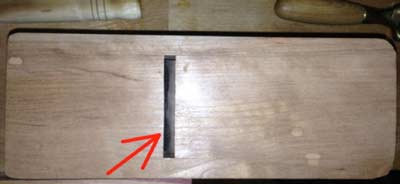
Creating a Trough for the Screw
You must remove material down the center of the bedding surface, creating a trough for
the screw (disregard if using an iron without a chip breaker) that mates the chip breaker
to the iron, allowing the iron to mate solidly against the wood. Mark the trough onto the
bedding surface so there is a little extra width for needed lateral adjustment, from the
top down to about 5/8" from the bottom. Make sure to hold your iron up to the bedding
surface and verify it will extend far enough to reach through the sole of the plane, even
after sharpening a number of times. Some prefer to remove this trough using a router table
with a straight bit, but I scribe mine by hand, and use my router plane to evacuate the
needed material. I use my Tite-Mark gauge to set the depth of the screw, and add a smidge
so it is slightly deeper and can't interfere with the iron/wood contact. Scribe this
setting on the top edge, so you know the depth at which to stop the router plane.

|
|
Figure 5 - Center section showing trough on bedding at red arrow.
|
Glueing Up
The next step is to lightly dry clamp the two sides to the center section. Make sure
they are lined up with one end flush to each other, while sitting on a known flat surface.
Put the front section in between the two sides and move it towards the rear until the
iron, when sitting on the bedding surface, contacts the front section about 1/16" above
the sole. Lightly clamp the front section in this position and use a sharp pencil to draw
the location of both middle sections on the wall area of both sides. The area between the
two lines, on each side, is the glue-free zone.
On a flat surface, put down either wax paper or a thin silicon mat, which will be your
reference surface for the glue up. Gather the clamps you plan to use in the process and
set them so they are open enough to go on easily, but close without a lot of work. Get
your glue out (I use a good yellow or white glue) and have a small brush or scrap of thin
wood ready to spread the glue. Set the plane pieces up on the surface, verifying one last
time the earlier triangle mark matches on all pieces. Take the top edge of each side and
push it away from the center section, so it lays on the surface with the glue surface
facing up. Put glue in the two marked areas of the first side, staying away from the
no-glue zone by 1/16” or so. Spread the glue and then lay the center sections into place,
being careful you don’t slide past the pencil marks. Carefully stand the three pieces up
on their sole area. Put glue on the other side section, using the same procedures. Stand
the second side up and carefully put it into position. While holding the back center
portion and sides flush on the flat surface, apply a clamp lightly to the center of that
section. Do the same with the front section; again making sure the center section is in
alignment with the two sides at the sole. Begin adding additional clamps over key areas,
starting with just behind the bedding surface, down close to the sole. After all of your
clamps are in place, verify that the bottom of both middle sections are flush with the
sides, and quickly adjust them if they are not. Next, you should clean up any major
squeeze-out, starting with the bedding/ throat area and the sole/mouth of the plane, which
is another critical area. Let the glue set for a minimum of an hour with the clamps on,
but if you have the time then you should let it set overnight. I have tried both and
luckily ended up with equally solid planes.
Installing the Cross Rod
Remove the clamps and clean up any additional glue that squeezed out on the sole. The
other areas will not matter since you will cut them away as you shape the plane, so there
is no reason to waste your time and energy. Using the sliding bevel gauge, set it so it
matches the angle of the bedding surface. Line the gauge up on the outside of a side,
matching it with the rear of the mouth, and draw a line. Draw a horizontal line
approximately 1-1/2” up from the sole, on the same side of the plane, in the general area
between the two center sections. Take the iron or iron/chip breaker you plan to use and
hold them so they are on the toe-side of the angled line you just drew. While holding them
in place, draw a small line along the back of the chip breaker in the area of the
horizontal line drawn earlier. This small line represents where the back of the chip
breaker will sit in the plane. Measure approximately 1/2” further away from the most
recent line, which will be the wedge thickness. I use a 3/8” mild steel rod as my
cross-rod, so measure another 3/16” (half the diameter of the rod, which is the distance
to its center point) from the last mark and where that intersects with the horizontal line
is the point to drill for the rod. Use an awl or another pointed tool to mark at the
indicated point to help align the drill bit for the starting location.
Set up your drill press with your 3/8” bit (if you decide to use the same size rod
material that I used in my plane) and with it turned off, set the depth stop so it will
stop shy of the table by 1/16” – 1/8”. This allows the bit to drill through the first side
and partly through the other so the rod can slide in, but won’t fall out the other side.
If you wish, you can choose to glue a dowel into the through hole after the rod is in
place. I’ve left mine open so far, but will likely plug it later.

|
|
Figure 6 - Cross-rod holes (actual rod at left) with bed angle in pencil on side.
|
Put the rod into the plane so it is at full depth, then make a little mark flush with
the outside of the plane. After removing the cross-rod from the plane, mark the actual cut
line about 1/8” in from the first mark, which will prevent the rod from sticking out. You
can cut the mild steel rod with either a hacksaw or a cut-off wheel in a Dremel tool. Just
take your time and work around the rod, until there is a little section holding it
together in the middle. With gloves on (since it can be quite warm) just bend it back and
forth a few times and it should snap free. Use a smooth metal file to remove any burrs and
clean up the ends before use.
Making the Wedge
With the cross-rod in place, put the iron/chip breaker in the plane and measure between
the iron and the rod. It should be approximately 1/2" but it is better to check before
cutting your wedge. Take the center triangular section from earlier and lay out the wedge
so so that the smooth surface will be against the chip breaker. Draw a line the distance
from the edge that you just measured, about 3/4” in from the narrow end. Measure over 2”
towards the thick end and make a second mark. Now measure up 1/8” – 1/4” from the second
mark. This will give you some choices. The wedge with the 1/8" slope will lock in tighter
than the one with the 1/4" slope, which can be a benefit, or a hindrance, depending on the
type of wood used for the wedge. You can test out both ends of the spectrum to find what
is best for you. Next, draw a line between the first and last mark. This is your basic
wedge shape. You can cut it out so either it is just that the full length is the basic
wedge shape, or you can make the top wider and round it over. If you go with the basic
wedge shape, you’ll be able to plane the top surface easily since it has a flat shape,
whereas the other shape will limit the tools with which you can adjust. If the wedge
doesn’t slip into the plane easily then you can either plane a few thin shavings from the
side or sand the side, so it doesn’t require force to enter the middle section. After
choosing your style and cutting it out, it is time to verify that it works properly. This
is accomplished by putting the wedge in with the iron, and lightly tapping the wedge.
Remove the wedge and look at the contact it made with the cross-rod. If there is a shiny
line all the way across the wedge, or shiny areas on both edges, you are golden. If not,
grab some 100-grit sandpaper and a small dowel or awl. The concept is that the high points
are those that make contact with the cross-rod causing burnishing, which result in the
shiny surface. Take the sandpaper and wrap it around the dowel or awl, using a light
touch, sand ONLY the small shiny areas.
|
|
Figure 7 - Wedge with initial contact sanded and ready for next test fit (missed early stage photos).
|
Re-insert the wedge, lightly tap, and check to see if any further adjustments are
needed. Repeat this process until you have a shiny band all the way across the wedge’s
face, or at least close to full width. This will hold the iron consistently in the plane,
making it much easier to adjust the iron and have it stay where you put it, without
needing to wail on the wedge.

|
|
Figure 8 - Wedge about finished with sandpaper around awl and alternate sander.
|
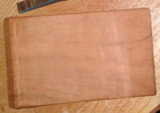
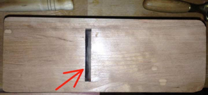
Cutting the Slot in the Sole
Now that the wedge/iron/cross-rod is working as a well-oiled team, it is time to remove
the extra material from the sole, which is the first part of the process that will
ultimately expose the iron through the sole. Before starting this section, put the
cross-rod into place, and put the iron in, but hold it backed off by about 1/8” and seat
the wedge. This will put the plane body into tension, and provide the best results. If
there are any section(s) of the sole that still have glue remnants, put some sandpaper on
a known flat surface and take a few careful light passes. Once all of the glue is gone,
you can shift to using a jointer plane (my preference) set for an extremely light shaving,
or you can continue using sandpaper. The main reason I prefer to use a jointer plane for
this process is due to the control it affords, lessening the chance I might accidentally
mess up the sole of my new wooden plane. Either way you decide to go, check your progress
very regularly so you can stop when the iron is contacting the front section about 1/64”
from the bottom of the sole.
At this point, remove the iron and cross-rod from the plane,
as you don’t want to damage either part as you shift over to using a fine file. You can
hold the plane body in the bench vise so you can focus a bit more on maintaining the
correct orientation of the file and its controlled little movements for this process. Work
the file up through the sole, only applying pressure on the forward stroke of the file so
you don’t chip the sole directly in front of the iron where it is most critical. Orient
the file so the front tip is leaning slightly forward towards the toe of the plane, as
this will provide the space for the shaving to pass when you finally have the iron reach
through. Make very small strokes with the file, starting at one sidewall and shifting over
incrementally until you reach the other. At this point of opening the mouth, check the
iron in the plane after every pass with the file. If you don't check often, then It's easy
to accidentally remove too much wood and end up with a throat opening that is too wide.
Many times, one side of the iron will start to show through the sole before the other. If
this occurs, completely avoid the area where the iron is already through and focus
attention on the other sections, trying to blend them into the completed portion. Stop
when you finally feel the iron through the sole, all the way across the plane. You might
be surprised, but if you look at the mouth on my plane from the sole-side with the iron
set for a nice light shaving you can’t see any actual opening. Since the shaving size
you’re aiming for is between .0005 - .003”, the opening only needs to be large enough for
the shaving to fit. If you keep the mouth tight, then it will provide the best support for
the wood fibers you are about to cut, as well as the best surface. Ultimately, with this
support being so close to the cutting edge, there is less of a chance for tear-out.
|
|
Figure 9 - Sole of plane with toe at left (red arrow is where cutting edge of iron meets throat, with no visible gap).
|
Adjusting the Blade and Using the Plane
You can now either practice setting your iron, and then work on the shape of the body,
or do this in reverse. I like to test the plane before going for final shaping; just in
case some major issue is hiding that will prevent the plane from working. To set the iron
for use, start by setting the sole of the plane on a flat board. Place the iron down onto
the bedding section and center it in the opening, remembering to also put the cross-rod
back in place. Now slide the wedge down into the plane and while pulling back on the iron
slightly, push the wedge firmly into place with your thumb. This should hold everything
together, even with the plane upside down (do this over a cushioned area, just in case
yours doesn’t hold the first time), so you can adjust the iron. From the top of the plane,
look down through the mouth to see if the cutting edge looks parallel to the opening. It
can help to have a bright light shining on a light colored board or paper as a backdrop
behind the mouth. If the iron isn’t parallel, lightly tap the side of the iron on the side
where the iron is closer to the front section, until it is parallel.
Now it's time to start
advancing the iron gradually forward, using a lightweight hammer, contacting in the center
of the back of the iron. Carefully feel the sole to determine when the iron is through.
When you can just barely feel the iron, set up a test board on its edge in your vise. Push
the plane down the board, with one side of the plane just barely on the board. Repeat with
the opposite side of the plane. If you are getting equal light/fluffy shavings from both
sides then you are finished setting the iron. If one side is producing a heavy shaving,
while the other has nothing, then use the lateral tapping of the iron to balance the
results. If you haven’t started getting any shavings, repeat the very light tap in the
back center of the iron and test again. The first couple of times it may take a little
longer to get the plane set for the shaving you’re after, but just like most things,
you’ll get better and faster with practice.
If you are having trouble getting a nice light shaving and after adjusting, it goes
from nothing to a thick shaving that almost jams, you might have a slight bump on the sole
of the plane, just behind the mouth. Check for this with a good straight edge, with the
blade slightly retracted but with the wedge tight on the iron. If you do find a bump, a
few light strokes with a block plane confined to the target area can resolve the issue
rapidly. An alternative solution would be to back the iron out very slightly and again set
the wedge, then take the plane to sandpaper on a known flat surface. Scribble with a
pencil on the area that is high, and when that is gone the sole is likely to be in good
shape. If using the sandpaper method, pay attention to the sole and when you have a
consistent scratch pattern across the whole sole, you should be done. I have also used a
technique that is somewhat based on Japanese planes, where a small band of wood is
retained at the toe, just in front of the mouth and at the heel of the sole, with the
remaining areas of the sole just slightly lowered. You can use a card scraper to remove
the areas to be lowered, which can help make the removal very gentle. Whichever method you
use, it’s a great idea to put a chamfer all the way around the sole. This will minimize,
if not totally prevent chipping while in use, and help deter blowout while shaping the
plane, especially when moving planes, spoke shaves, or draw knives in the direction
towards the sole. Remember to keep watch on the chamfer size as you work towards your
target shape, as it will shrink with additional wood removal. I had to re-establish the
chamfer on my plane multiple times while working from the squared-off rear section to the
hand-friendly continuous curve.
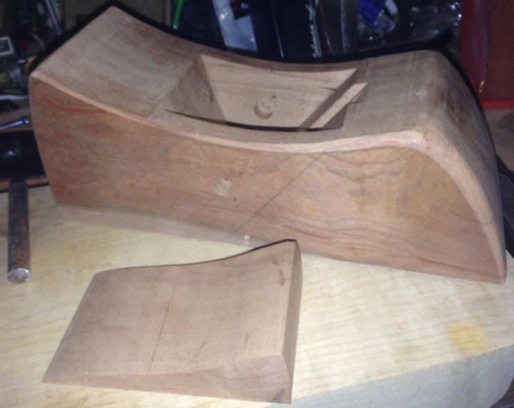
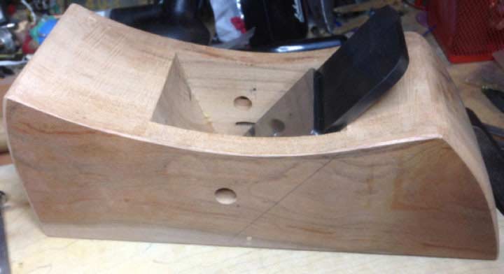
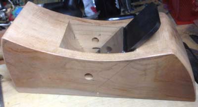
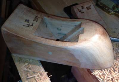
Final Shaping of the Plane Body
Now that you have a functional plane, you can decide what type of shape you want for
the body. This can be as simple as knocking off the sharp edges with some sandpaper or
totally reworking the shape to fit your hand like a glove. After you draw the shape on the
side of your plane’s body, remember to remove the cross-rod, wedge, and iron from the
plane. The bandsaw is an ideal tool to make the shaping cuts to a point. While you can cut
the body to its complete side-view shape, don’t try to remove any of the rear corners. If
your design is sloped it will require the body to be held up at an angle on it’s heel in
order to create the almost oval shaping. The front of the body is almost vertical, so it
is another good candidate for the bandsaw. When engaging the bandsaw blade, remember to
keep the wood in good solid contact with the table, or you can put yourself into a
dangerous situation. Please stay safe!
|
|
Figure 10 - Plane shape directly from bandsaw with light rounding on edges.
|
|
|
Figure 11 - Plane shaping midpoint. Rear curved front still square.
|
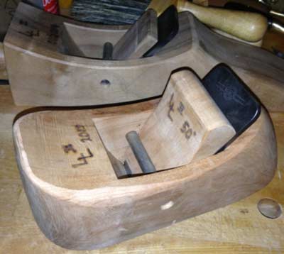
|
|
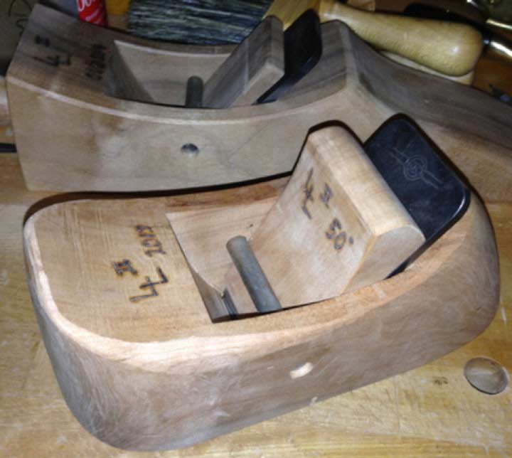
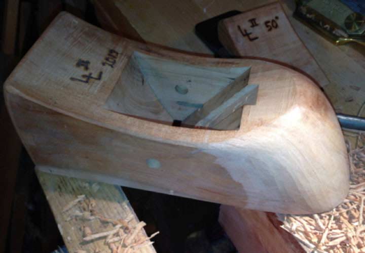
Figure 12 - Plane is now in a final shape that feels great in the hands. Plane for 1-¾” iron is seen in background in Walnut.
|
After completing the work on the bandsaw you can shift over to spoke shaves and draw
knives to make a somewhat quick work of the shaping. You can obviously use anything from a
bobbin type sander to a stationary belt sander to hand sanding if you don’t have any of
these tools, or just don’t feel as comfortable with these tools. Ultimately, use whatever
tools that will let you complete the project.
I hope you found this article interesting and will try your hand building a plane using
a Hock plane iron. Just take your time, think through each step, and you’ll likely be
successful. Please let me know if you have any questions or comments.
Lee Laird is a regular contributor to the Highland Woodworking blog. (You can
read his contributions
HERE
). He has
enjoyed woodworking for over 20 years, and is retired from the USPS. You can email him
at
lee@lie-nielsen.com
or follow him on
Twitter
.
Return to
Wood News
front page