Building an Electric Bass Guitar: Part 5 - Installing the Frets, Bridge, and Saddles
by Lee Laird
Click on any picture to see a larger version.
CLICK HERE
to read Part 1 of the Electric Bass Guitar Build - Design Considerations
CLICK HERE
to read Part 2 of the Electric Bass Guitar Build - Creating the Neck
CLICK HERE
to read Part 3 of the Electric Bass Guitar Build - Making the Fretboard and Neck from Scratch
CLICK HERE
to read Part 4 of the Electric Bass Guitar Build - Gluing the Fretboard, Cutting the Headstock and Installing the Tuners
This is the fifth part of a multi-part article, relating to building a Bass from scratch. The previous sections are available by clicking the links above, for anyone wishing to either start from the beginning or to just see what took place earlier. On with Part 5!
Installing the Frets
It is time to install the frets into the slots I cut into the fretboard back in
Part 3
of this build. I wanted to bring up a couple of related things that may need a bit more detail. I used my Dovetail Saw, which I re-purposed by changing the filing of the teeth from Rip to Cross Cut. I made a test cut in some spare wood so I could test the new fret wire directly. This was to make certain the width of the kerf was large enough to accept the fret wire, while still being narrow enough so the barbs on the tang would hold securely once the wire was driven down into the kerf. I'd really hate to waste a nice fingerboard after going through all of the layout procedures and sawing, only to determine the slot was incorrectly sized for the frets.
Fret wire is usually purchased in 2-3 foot sections, and some of the choices available are: height of the portion that sits above the fingerboard, width of that same section, tang length and width, as well as the material from which the fret wire is made.
When I began playing guitar, most fret wire was made from a similar material. Somewhat recently, retailers have begun to offer fret wire made of stainless steel, which many believe should last almost as long as your guitar/bass. The long standing materials they've previously used for fret wire would wear down or get low spots in a fairly short period of time, obviously depending on how much one played, the pressure applied and the amount of vibrato used. The only real negative caveat regarding the use of stainless steel for frets is that its strength makes it quite a bit harder to work with during installation.
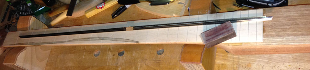
To start the fretting process, I hold the tang (above the barbs) with a large pair of side cutters, and gently bend the wire so it will have a slightly tighter arc than the fingerboard. This will help the ends of the fret wire stay down against the fingerboard when the wire is seated. I lay the tang of the wire into a slot, and with the loose end just hanging over the opposite edge of the fingerboard, I cut the wire just proud of the side closest to me. This leaves me with a piece of wire that is perfect for that one specific slot, since the fingerboard flares from being small at the nut to large at the bridge. I prefer to seat each fret immediately after cutting, so I don't mistakenly use the wrong piece. Be sure to check the tang of each cut fret as the cutting process can sometimes bend the corner of the tang, which could prevent an easy installation.
|
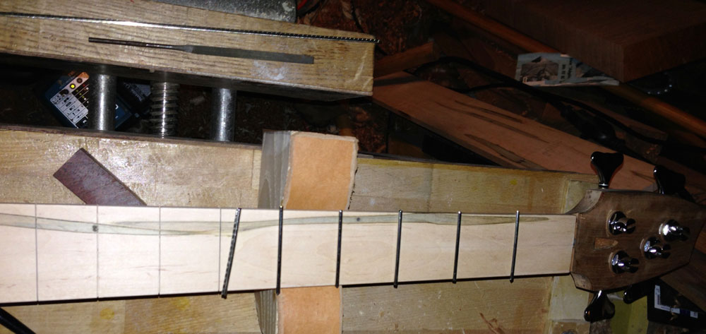
To install a fret, place the fret wire so the tang barely sits into the slot in the fingerboard. If you cut the slots with the correct sized saw, the barbs on the wire will prevent it from going very deep when sitting on the fingerboard. While holding the fret wire in place at one end (with each fret end just proud of the fingerboard) lightly tap on one end of the wire with a brass-headed hammer. As the first end seats, just work your way across the fingerboard with more light taps until the fret is completely seated. Remember, you are making a fine instrument, there should be no need to hit the frets with a 6-lb sledge hammer!
The above steps are repeated until all of the frets are in place. As an alternate method you could go through and cut all of the frets to their respective size first, and then come back and seat each one, but I've mentioned the possibility of errors with this method. Choose whichever method that works best for you.
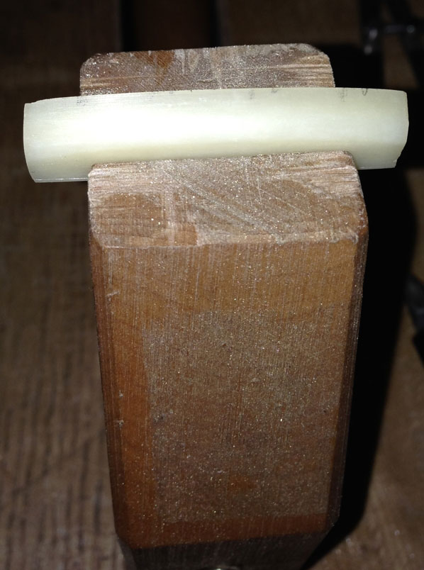
Next, I like to apply some super glue to the frets so there is even less chance the frets will shift or lift out. To do this I have a small piece of dense tropical hardwood, with one face the same shape as the fingerboards radius. I applied a piece of teflon tape to the curved side in order to prevent any chance the block might get glued to the fingerboard. I place this block so the teflon covers the fret wire from side to side, and then hold it firmly in place with a non-marring clamp. While the block and clamp are in place, I flip the neck on its side, so I can drip some super glue down into the same slot as where the clamped fret is located. I use super glue that is about the consistency of water, so it doesn't just sit on the edge of the neck, but actually wicks down inside. I spray a super glue setting material onto the edge of the neck, and then rotate the neck so the other side is facing upwards. Repeat the same process on the second side. Now you can release the clamp and move on to the other frets.
|
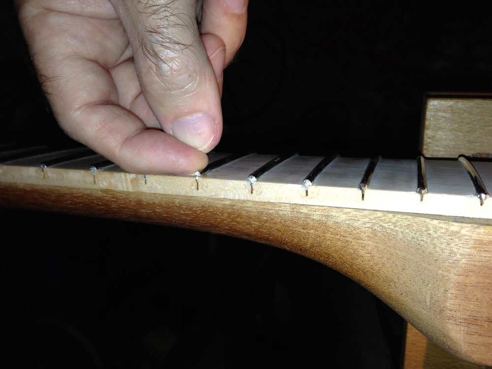
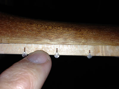
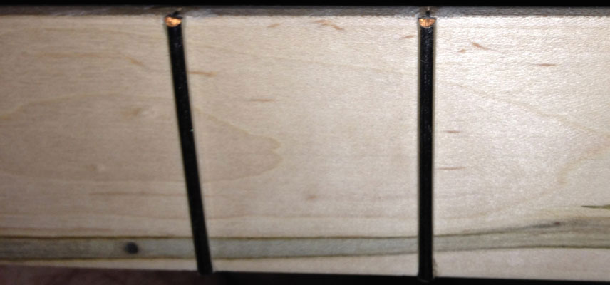
During this bass build, I had a couple of frets that were misbehaving. I noticed one end of the frets wasn't staying down against the fingerboard after the super glue was applied:
|
|
My fingernail easily fit under the raised end of the fret
|
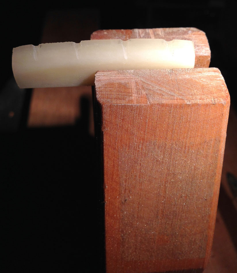
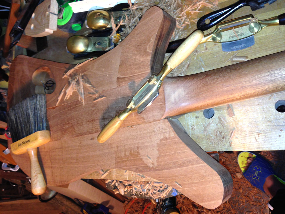
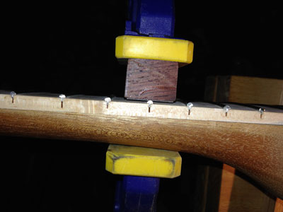
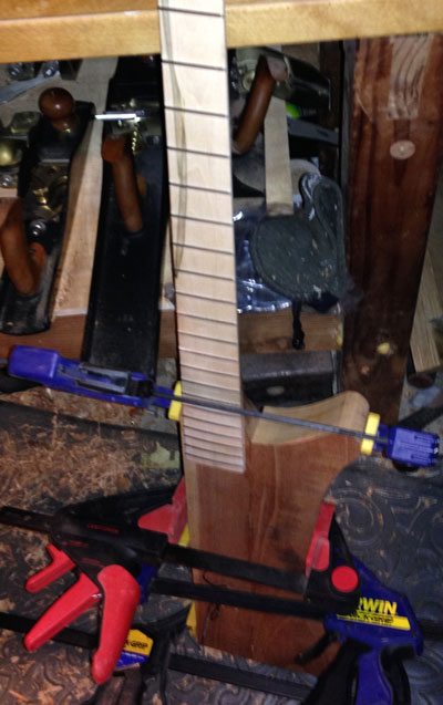
When I placed the jig back onto these frets and applied the clamp, the frets sat down against the fingerboard, as intended.
|
Block placed directly over the problematic fret,
and pressure applied with the clamp
|
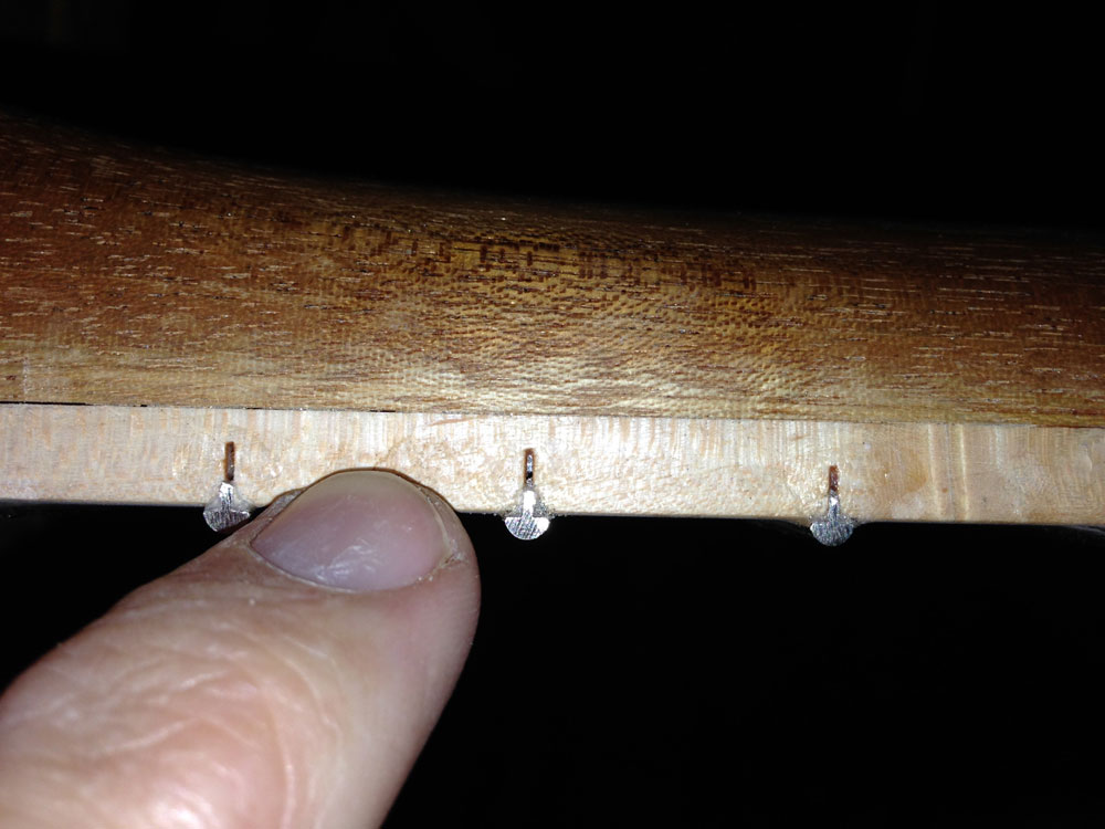
I re-applied some super glue and the setting agent, and kept the clamping pressure on each of the problematic frets for a few extra minutes to make sure the super glue was cured completely. When I removed the clamp, the end of the frets stayed exactly where they were intended.
|
Fret was fixed and retained its shape after allowing to set
under pressure for a longer period of time
|
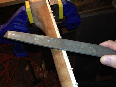
After the frets were all solid, I used a somewhat coarse file to remove the majority of the excess wire beyond the edge of the fingerboard.
|
|
Using a file to remove gross extra fret material
|
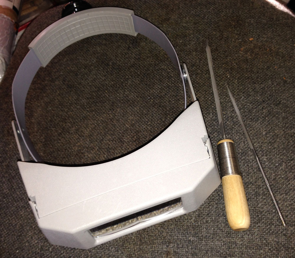
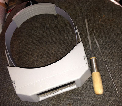
I stopped as I got close to the fingerboard and came back in with smaller triangular files, starting with a medium grit and finishing up with a very fine file.
|
Two triangular files and a MagniFocuser to better
see the fine fret work
|
This same file was also useful when filing the small angles on each end of the fret wire, and blending the small corners from that process. Follow this file work with sandpaper of subsequently smaller grits, up to around 800 grit. This will create a very nice and comfortable feel on the neck.
|
30-45 degree angle filed on the end of the frets
to make it more friendly for hands
|
All of the frets need to be in the same plane when the strings are under full tension so there are no high or low frets. If any are high or low you will have positions on the fingerboard that cause a buzzing sound, or may not allow a certain note to be voiced. Similar to flattening a board, the longer the straight reference tool you use, the better your chances are of good results. This full process is beyond the scope of this article, but there are many sources available, including books or online, including StewMac.com.
Bone Nut Shaping
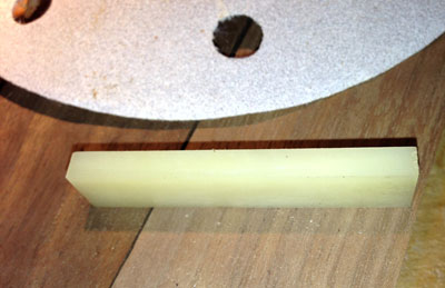
Now that the frets are good to go, I have shifted my focus to shaping the bone nut I'll use on this bass. When I received the nut, it was a small rectangular piece of bone:
|
|
Bone nut blank as received
|
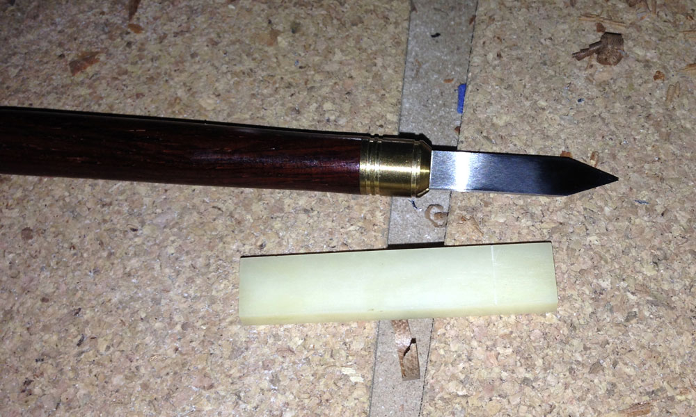
To start, I measured the nut while it was in its slot, marking it just slightly long so I could use a file and sandpaper for an exact fit.

|
|
Marking knife used to scribe length of the nut
|
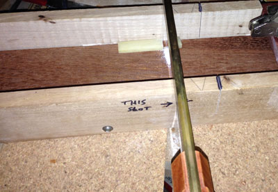
I used the same jig I made to accurately cut the slots in the fingerboard. There was no reason to change to a different saw either, as the fine cross-cut I used for the slots, leaves a decent surface.
|
|
Nut cut to length in jig
|
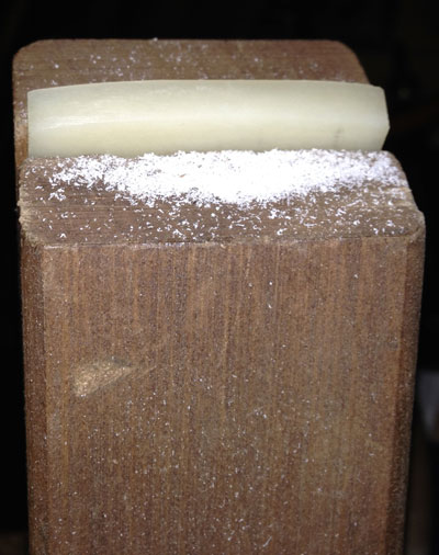
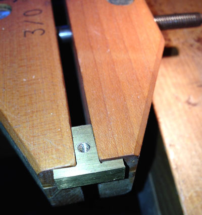
I shaped the nut so it would follow the radius of the fingerboard as well as adjusting it so the string passing over it would only touch directly above the edge of the fingerboard that meets the nut. Both shaping processes were accomplished with medium and fine flat files. I held the nut in a wooden screw clamp while holding the clamp tight in the front vise on my bench. The angled back area on the outside of both jaws (in the wooden screw) gave me easy access to the nut. (This process has also helped elevate the work, which makes it less stressful on my back.) I left the nut smooth from side to side, as I'll mark the notches for the strings a bit later after having the bridge in place, too.
|
Nut shaped back at about a 45-degree angle, along with
slight curvature from side to side.
Held in a wooden screw vise
|
Bridge and Saddles
There are quite a few bass bridges available that are little more than just a thick piece of foil bent into a shape. Ok, that is somewhat of an exaggeration, but some really don't seem to do a good job of aiding in the tone or sustain. I bought a used BadAss (really, that is its name, not me using colorful language) bridge for the bass, as I've always liked the extra mass they add, as well as their solid performance. This bridge was a steal, as they reduced the price since it didn't have the four saddles, the adjustment screws, or the springs. So, basically it was just a nice piece of metal, with some holes in it, and a few grooves.
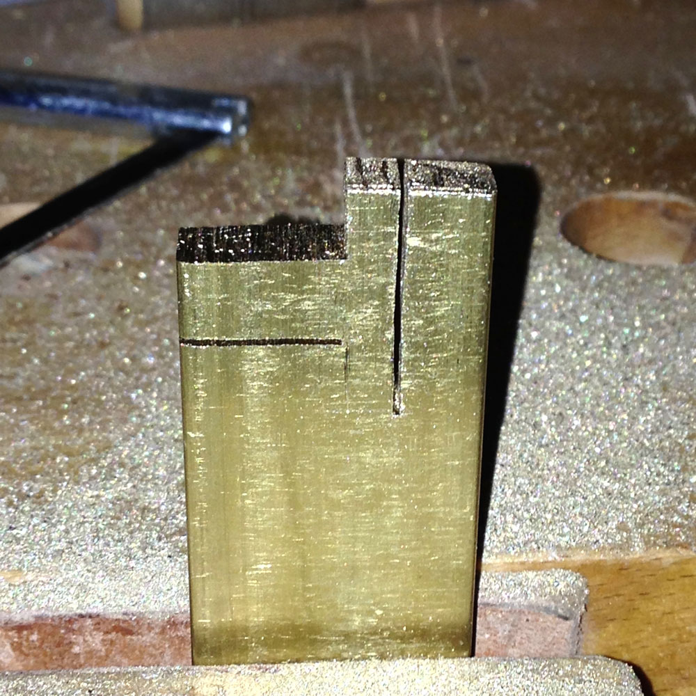
The saddles and other pieces are available from a few other companies, but I decided I would create my own saddles out of some thick brass. I found a company that sells small bars of brass, and bought one that was 1/4" thick, 1" high and 12" long. I took some measurements from the bridge, so I could mark them out on my stock. Since brass is fairly easy to work, the majority of my work was with hand tools, with just a single visit to my drill press. After marking out the saddles, I cut them out with a very small saw that was somewhat similar to a hack saw. I made sure my layout left enough extra material so I could fine tune all aspects to have a solid fit into the bridge.

|
Partially cut out saddle, still attached to the
long stick of brass
|
I used files to perform the majority of the shaping on the saddles, and kept testing my work directly against the bridge's body. I also left the individual saddles a bit tall, as I wanted to have extra material for the vise to grab while I drilled the hole(s) for the adjustment screw(s).

|
|
Initial testing of saddles straight from the saw
|

|
|
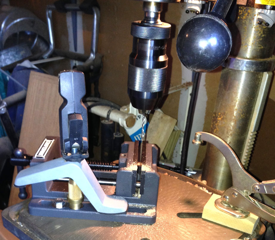
Vise used on drill press to hold each saddle during drilling
|
|
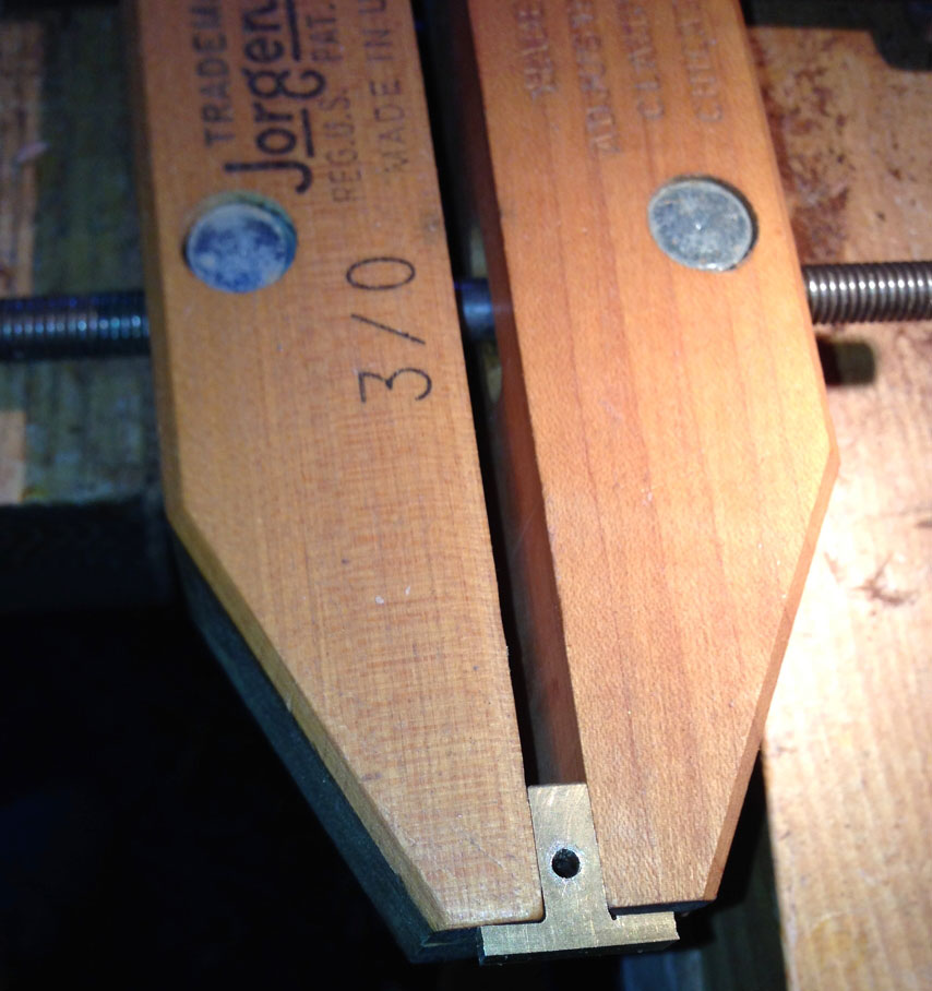
Saddle held in wooden vise with hole, but not threaded
and the same after threading (tapping)
|
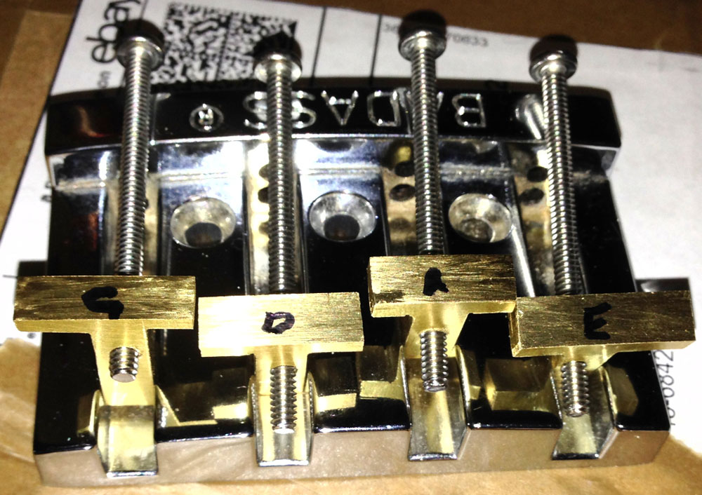
I used a tap in each hole to match the pitch of the screws I bought at the hardware store. This again was really simple since the brass doesn't present a lot of resistance. When all the saddles fit their respective slots properly, I trimmed the extra length with the same saw and then I filed the ends until I was happy with the fit. The saddles currently have a basic shape, which is a good starting point, but I'll still create a notch in each later so the strings stay exactly where they belong.

|
|
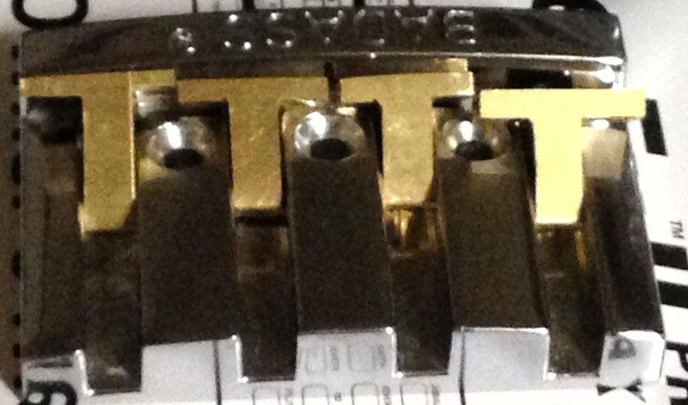
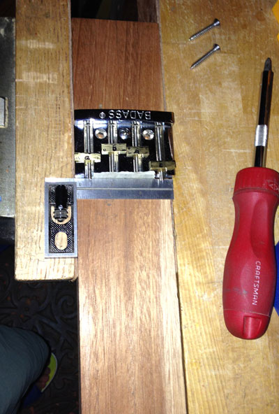
Saddles on screws, sitting into bridge slots
|
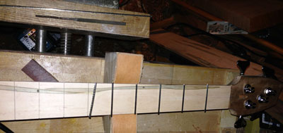
I checked my measurements, as to the location where the saddles would make the proper scale length, and marked for the installation of the bridge, leaving some room to adjust both short and long. I initially marked only for the center attaching screw, and then drilled a pilot hole just deep enough to snug up the bridge. Before trying to mark the two outside holes, I installed the center screw, letting it keep the bridge steady while I finished marking.
|
|
Clamping arrangement
|
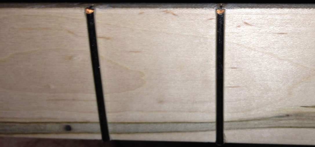
After drilling the other two pilot holes needed to attach the style bridge, I installed all three screws and checked that the bridge was still in proper position. I installed the bridge with a very slight cant, putting the low E side a slight bit further from the nut than the G. I put the nut into its slot and put the strings into place. With some tension on the strings, I shifted each string at the nut and the bridge until there was an even spacing across the fingerboard and from both sides. While the strings were in place, I made small tic marks on each side of the four strings at the nut. I placed the nut back into my clamping arrangement (above) and using a very fine round file, created the notch for each string. I used a different section of the file for each string, as the file thickness grows as it gets closer to its base.

|
|
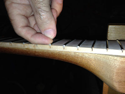
a.
|

|
|
b.
|
Photo (a.) above shows the pencil marks for the notches. (b.) shows the finished notches.
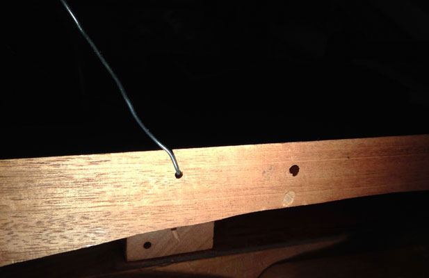
I made a light pencil mark along the front and the rear of the bridge, so I would know the exact area covered by its base. I needed to have the exact location of the bridge and its screws, so I could drill for a ground wire without accidentally drilling through one of the screw locations. As added information, the ground wire connects to the ground side of the jack, or to the back of the potentiometer. This prevents a nasty hum that would otherwise exist when plugged into an amplifier and the strings are not grounded. If you've ever played an electric guitar or electric bass, and there was a loud hum when your hands were not touching the strings, it was either missing the ground wire or the connection was broken. The ground wire basically sits underneath the bridge, using the compression of the bridge to maintain solid contact when the three attachment screws are tightened. Since this build is a neck-through design, I went about making the path for this wire a bit different than the one on the Les Paul. I knew I wanted the wire to exit the side of the main section of the neck, close to the center of its thickness so there would be no chance of hitting it while removing wood during the shaping process. I chose a drill bit just larger than the wire I was using, and drilled in towards my target from the side. I then drilled down from the top at a slight angle to meet the first hole. All the luck was with me, as it matched up nicely. Now came the fun part! I needed to line up the lower wing of the bass body, so it would be in the same position when it was glued, and then mark and drill for the hole to continue on to the control cavity, which would complete the path for the ground wire. I used a solid core wire, for the ground wire and it doubled as a marking tool when the lower wing was in place against the center section. After drilling at the marked location, the holes aligned beautifully.
|
|
Ground wire fed through the hole in the center section of the body
|
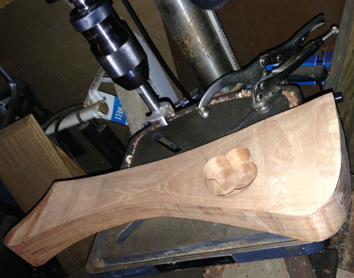
I made a similar hole, although a bit larger in diameter, for the wires that will go from the pickup to the volume knob. I used the same techniques as above. After measuring for the location where the holes would terminate, I laid out a small control cavity, and with the lower body section laying on its flat top, drilled it out with an awesome
Forstner Bit
. The bit was made in Germany and cuts through wood like butter. I set the drill press table so the bit would stop just less than 1/4" short of it, at full extension. I could have chosen instead to set the stop so the bit would only come down a certain distance, but my decision completely removed the chance that the stop could slip at the most inopportune moment, and I'd have a nice big hole through the face of the bass's body. I'd likely also have ruined the bit, since I hadn't bothered to align the bit with the center hole on the table. After all was said and done, both of the holes I drilled as wire pathways merged nicely into the control cavity.
|
|
Control cavity on rear of bottom body wing
|
Now I was to the point where I could glue the two wings onto the center section of the bass. I fed a wire through both of the holes that I had drilled previously to make certain they didn't get glued shut by accident. I'm a bit cautious so I measured all of the holes drilled with my
Festool Domino
, and compared it to the actual domino's length. I didn't want to get glue spread and start driving the parts together, only to have the domino hold the parts away from each other slightly. Everything looked fine, so I put a small amount of glue on the end of two dominos, and drove them into the holes I drilled with the domino set for a tight fit. I spread glue on the mating side of the center section, and a little into the slightly elongated domino holes, and then brought the two pieces together. I made sure my earlier alignment marks matched up, and the wires were still capable of sliding through freely.
|
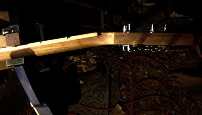
Bottom wing glued to the center section,
with clamps in place
|
I clamped them together for about an hour and then repeated the gluing process on the other side wing. This time the clamps went fully across the bass's body. I left the clamps on for almost a full 24 hours, letting the glue do its thing.

|
Second wing glued on, making the full body.
Clamps shown in place
|
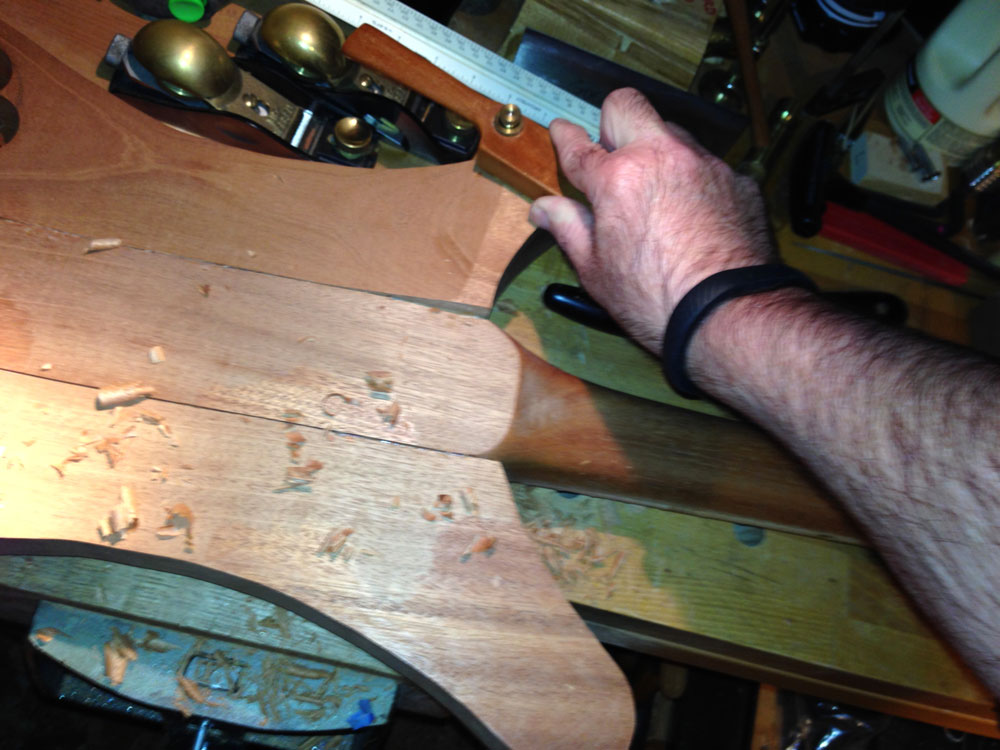
As I'd earlier removed some of the excess wood on the back of all three pieces, now it was time to start blending them together. There were a couple of locations where there was a fairly large discrepancy, but I still decided to take it down slowly with some spokeshaves, rather than trying to hog it off with a different tool and have it dive down beyond my lines. I'll still use my sander, when all the parts are of similar thickness, but find the hand tools are easier to control and more satisfying to use.

|
Using a low angle spokeshave single-handed,
to remove wood across the grain
|

|
The two front horns are brought down close to the thickness of the
center section, and more blending will ensue.
|
I noticed the bass isn't as balanced as I'd expected, with the body overwhelming the neck, even with the tuners installed and the bridge off the bass.
I've decided that next time I'll adjust my Bass's design slightly and remove some length from the bass's body, helping the overall balance of the instrument. Check back in and I'll share this and some more details regarding how the bass plays as well as some final photos and thoughts.
I hope you enjoyed this article and please let me know if you have any questions or comments.
Lee Laird has enjoyed woodworking for over 20 years. He is retired from the U.S.P.S. and works for
Lie-Nielsen Toolworks as a show staff member, demonstrating tools and training customers.
You
can email him at
lee@lie-nielsen.com
.
or follow him on Twitter at
http://www.twitter.com/is9582
.
Return to
Wood News
front page