|
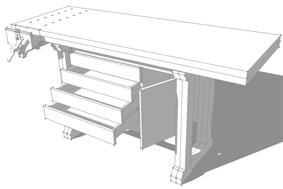
The traditional style workbench we will draw in this month's article is designed to utilize
standard framing lumber, with "half-lap" style joinery to make up the base structure. The work
surface uses prefabricated butcher block counter tops available from your local "Swedish home goods
mega-store" to make a durable, stable bench top at an economical price. To finish, we will outfit
the bench with a front vise and cabinet storage to keep all your tools organized and close at hand.
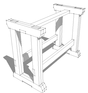
Legs
All the parts of the workbench base are made from standard framing lumber. I have used 2x4s as
they seem to suit the scale of my bench. You could use larger lumber employing the same methods if
you feel a bit more heft in the design would better serve your needs.
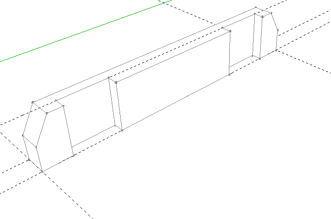
Start with the
rectangle tool
, drawing a rectangle 1-1/2" x 20-3/4". With the
push/pull tool
, raise
the face 3-1/2" (the width of a 2x4). Create
construction guides
on the wide face 2" from either
end. From each of those two guides make two more guides 3-1/2" in. This is going to be the location
of the lower leg joint. Draw rectangles at both of these joint locations and push/pull in 3/4". This
makes one half of the half-lap joint. With the
line tool
draw a line that will determine the chamfer
on both ends of the foot and push/pull these areas away to create the chamfer profile. This
completes one half of one foot.
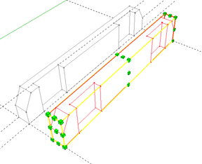
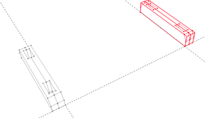
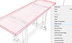
Select the entire foot
by triple clicking on it, right click and
choose
Make Component
from the menu. You can simply press "create" and not worry about all the
options in the dialog box. With the foot component selected,
move a copy
over several inches. With
the copy selected now, choose your
scale tool
. Using one of the grips located at the center of the
face of the foot, scale the foot to a value of (-1). This should result in a part that is a mirror
image of your original part. Using the move tool, click on an edge point of your foot that you can
place on the corresponding location on its mating part. You should now have a completed foot. Select
both halves of the foot and move a copy of them over approximately 40". Now select all four foot
components and move a copy up in the blue axis direction. With all four copies selected, use the
scale tool to scale to a value of (-1) in the blue direction. This will make the upper supports for
your table top. With all four copies still selected, right click and choose "Make Unique" from the
menu. This makes new components of those selected, separate from the original four. Any changes you
make to these components will have no effect on their "foot" counterparts.
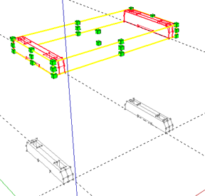
Double click one of the foot components. You will see that most of the model has faded, indicating
you are in the edit mode. Viewing the foot from the bottom, draw a rectangle in the middle of the
foot that you can push/pull in 1/2" or so to create pads for the feet to sit stable upon on unlevel
ground. By editing one foot, the change should occur on all instances of that component. Draw a guide
33-3/4" up from the point where the feet rest on the ground plane. This will be the top of the table
supports and the underside of the 2-1/4" top, giving you a 36" finished work height. You can adjust
this height as you see necessary.
Select all four table top supports, and using the move
tool, move them up to the height you laid out with your construction guide. With the feet and
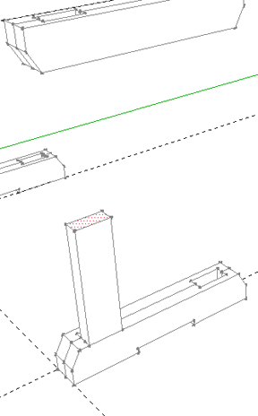
table supports complete, we will make the legs that will support the tool cabinet. Looking at the
top of one of the feet, draw a rectangle 1-1/2" x 3-1/2" over one of the half lap joints you created
earlier. Push/pull this face up to the bottom of your table supports. To create the mating part of
your joints,
select a view
that allows you to look down into the mortise in the table supports.
Draw a line where the edge of the joint in your table support intersects with the center line of
your vertical support. Now push/pull the visible half of the vertical support up to the top of the
upper support completing the half lap joint. Repeat for the bottom of the vertical support. Once you
have completed the upper and lower joint, triple click the vertical support to select the entire
part, right click and make it a component. The process for copying and flipping is the same as used
for the feet and table supports. Copy and scale to make one complete leg support. Then choose both
leg halves and move copies to the other three leg locations.
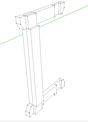
Cabinet
The cabinet and stretchers work together in this design to keep the workbench from racking to
either side under a load. If you are not going to have a cabinet in your bench, I would probably
recommend using 2x10s or 2x12s for the lower stretchers.
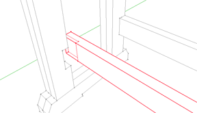
Double click one of the vertical supports to edit. The bottom of the lower stretcher is 5" from
the top of the foot of the bench, so I make a construction guide to determine this measurement. From
there I create another guide 3-1/2" higher (the width of my stretcher). Using the line tool, draw a
line where each of the construction guides cross the vertical support you are editing. Then
push/pull the face in 3/4" to make one half of the joint where the stretcher will be located. You
should see that the other instances of that component in your model were also modified, creating
recesses for both of your lower stretchers/cabinet supports. Use the rectangle tool to make one of
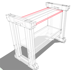
the stretchers with the joint details using similar techniques discussed earlier. For the upper
stretcher, locate a recess on the bottom of the table top supports midway between the vertical leg
supports. Select one of the lower stretcher components and move a copy to the location of the upper
stretcher. With the move tool, hover over the end of the stretcher component. You will see grips
appear enabling you to rotate the stretcher to the proper orientation. Once rotated, move the part
into its final location seated in the lap joint on the underside of the table top supports.
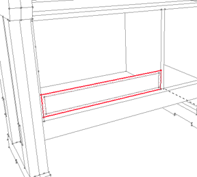
With all the stretchers in place, draw a rectangle for the bottom of your tool cabinet. Push/pull
the face up 3/4", select all and make component. This represents the top and bottom of the cabinet.
With the move tool, and the cabinet bottom selected, click once on the cabinet bottom. Move a copy
in the blue direction. While moving in the blue direction, hold down the shift key. This will lock
you in that direction so you can move your cursor to the bottom edge of the upper stretcher, and
click again to place the copy. You should see the copy is placed flush against the bottom of the
upper stretcher. Create the sides and middle divider for your cabinet in the same way. The cabinet
I designed is divided roughly into thirds with the drawers taking up two-thirds, and the cabinet
using one third.
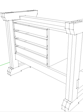
Drawers
To begin the drawers, start by drawing a line on the inside front edge of the cabinet side.
Right click on the line and choose "Divide" from the menu. Move up and down to change the number of
line segments to create. I divided the line into four segments. Use the height of the bottom line
segment to draw a rectangle across the opening where the drawer will be located. With the
offset
tool
on the face, offset a rectangle 1/2" in from the edge. Select and delete the line you drew in
the first step along with the other three lines that made up the rectangle you drew in the next
step. You should now have a face that is approximately one quarter the height of the opening and 1"
narrower than the width, to allow for standard full extension ball bearing drawer slides. Push/pull
the face into the opening 1/2" to complete the drawer front. Make it a component and move a copy to
create the back of the drawer. You will need to scale the drawer back so the inside face of the
drawer faces in. This is so that when you make the dado for the drawer bottom, it is on the inside
face of the back of the drawer box. Make the side of the drawer between the drawer front and drawer
back the same way. Make it a component. Move a copy and scale to make the other side. Edit the
drawer parts by making a 1/4" dado 1/4" to 3/8" from the lower edge for a 1/4" plywood bottom. Use
the rectangle tool, and push/pull to make the plywood bottom. Make the drawer bottom a component.
Once you have finished the entire drawer, select all of the drawer parts and make them a component.
You can now move a copy of the complete drawer box to the top location, then press "/3" then
enter. This will place two more copies equally between the top and bottom drawer. once your drawers
are done, use a similar technique to make the drawer fronts and the cabinet door.
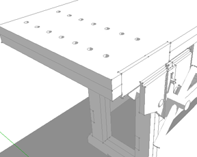
Work Surface
The work surface for this table is made up of two pieces of butcher block counter top laminated
together. Alternatively, a number of companies offer a large variety of workbench slabs.
The process of modeling the top is pretty straightforward. Draw a rectangle from one upper support to
the other. Push/pull the face up to the thickness of your work surface. The prefab counter tops I
detail in my model are 1-1/8"thick. Push/pull out to either side about 14" and 2" to the front and
back. Triple click to select the whole top and make it a component. Move a copy up, doubling the
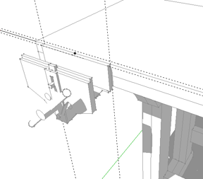
thickness of the work surface. The front vise I use in the model is the
Anant no. 53
available at
Highland Woodworking.
There is a model herein the 3D Warehouse
. Download the vise to your model and
edit your bench top to mount the vise flush with the front edge. I also added some dog holes in line
with the front vise for clamping larger parts. This three point clamping design will allow you to
hold round or irregular shaped parts.
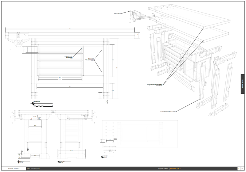
Construction Drawings
For this workbench I have attached a
PDF file
that you can download to a flash drive or CD and
take to a print shop for a
full set of measured drawings
for you to use in the work shop. You may
find these files difficult to view on your computer because of the fine line weight of the drawings,
but I believe they are appropriate for the full size prints (24" x 36"). These were created in
LayOut, which is a program used for presentation of SketchUp models, and comes as part of the
SketchUp Pro package. As most of you probably use the free version, I am not going to offer any direction on
how to use LayOut. However each of the future projects we build will be accompanied by
these measured shop drawings. I have tried to include most of the measurements required, and over
time I will refine the details in these documents to make them as organized and
informative as I can.
As always, feel free to
send me an email
with any comments,
questions, or suggestions.
|
|